In the MP4247 datasheet the VOUT_COMMAND is used to set the output voltage.
The maximum output voltage is specified as 21.47V (21470mV).
When setting the “output voltage” you are actually setting the internal reference voltage which is then multiplied by the feedback ratio to determine the output voltage.
Since the feedback ratio is 10 and the maximum voltage is 21470mV the internal reference voltage should be set to:
Internal reference voltage = 21470mV / 10 = 2147mV
The 11-bit DAC when set to 0 actually sets the reference voltage to 0.1V (100mV).
Therefore this value should be subtracted from the voltage we want to set before converting it to a binary value.
So the new offset internal reference voltage is:
Offset internal reference voltage = 2147mV - 100mV = 2047mV
Converting this value to binary we get:
DAC value = 0b0000_0111_1111_1111
Therefore as shown in “Figure 8: PMBus Message Format” of the datasheet to set this value, I should first send the low byte followed by the high byte.
So send the MP4247 address, then send the VOUT_COMMAND code, then send 0b1111_1111, then send 0b0000_0111.
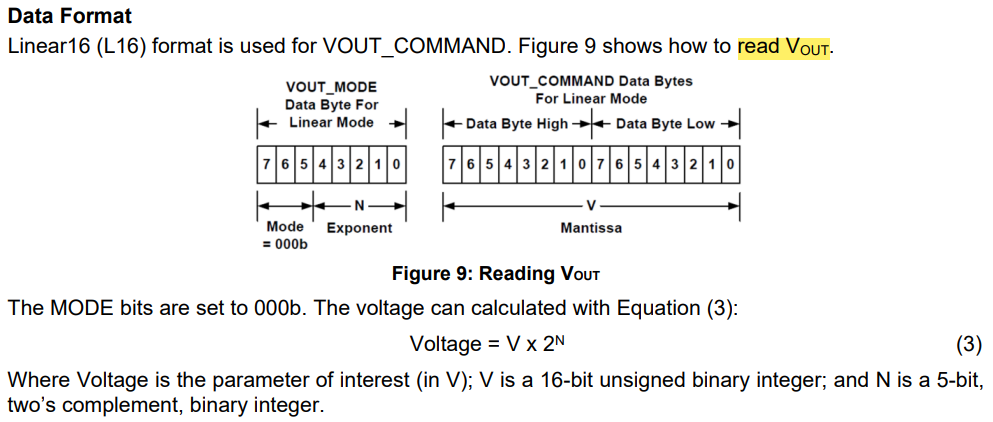
However I then noticed “Figure 9: Reading VOUT” which confused me as this indicates there is another 8-bits for VOUT_MODE which is not mentioned anywhere else in the datasheet.
So do I need to worry about this 8-bits for VOUT_MODE?
Is this a mistake in the datasheet?
Thanks!