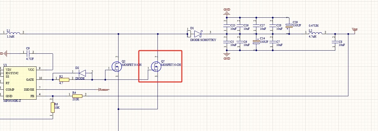
I’m using MP3910 to create a boost solution for 30V 7A application, while the chip has been able to do it’s work, but the mosfet is generating extensive amout of heat that I need a small fan to cool it down. The fet I’m currently using is IPB026N06N by infineon. So instead of using a fan, I thought using 2 fets might spread out the load so it won’t generate too much heat.
I read the datasheet that the chip have a 1A 12V MOSFET Gate Driver, that means I could sort of drive 2 mosfets for this application?
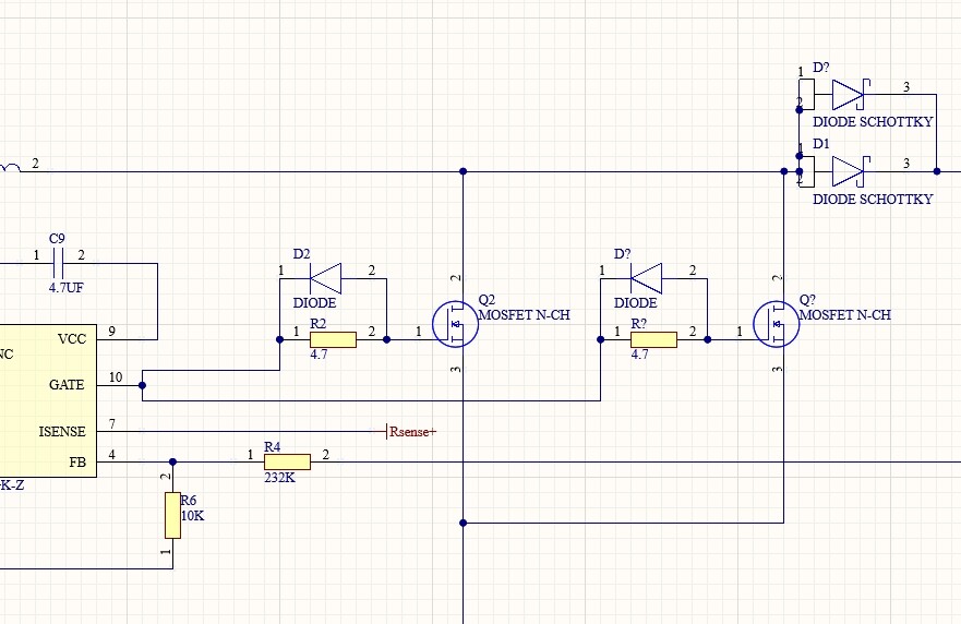
if that is applicable, is my schematic here correct? a review is appreciated.
It is a good idea, two mosfets cut the dissipation in half, so that is a plus and the thermal resistance is cut in half as well. So temp rise is reduced roughly by 4X.
Generally ap notes for Fets advise that you don’t just connect the two gates as shown some weird HF oscillation can occur instead use a separate RD network for each FET.
I am just telling you what I read, ferrite beads also make it look like you really know what you are doing. I just ran through this and am doing exactly what you have shown.
A first note… you are using a 80A MOSFET on 7A and its getting hot. Think about it… The MOSFET should be cold otherwise it will melt at 80A. What I suspect is that the losses are causing the thermal is. Ciss, Coss are both high. Sometimes, you need to look at the tradeoffs, its not just a low Rds, if you look at the SIR462, its 1nF, 260pF, 95pF, turn on/off 20nS, Qg=20. IPB026N06N is 3.8nF, 890pF, 220pF, turn on/off 11nS/60nS, Qg=118. Sometimes you have to trade Rds for losses, a seemingly worse device, shines when you added the losses in. I’ve actually built a 5A buck before, barely 10C temperature rise. Of course I don’t know what your input/output or peak MOSFET current are.
From a quick calc… MOSFET current approx. 30 A. At 62 K/W - 2.7 W loss, 168 C temp rise. Two MOSFETS will make it 84 C temp rise. That’s assuming a minimum PCB solution. All in all 270 W (30V, 7A) power delivered (assuming no losses - and there will be lots of losses). Do my numbers make sense to you?
Four MOSFETS, 42 C temp rise, These are just approximates, I used an online calculator and 200 kHz switching frequency. I suspect a fan and a good heatsink will be required regardless of the number of MOSFETs used.
I would also look at doing something different, for this sort of power, use multiple phases, it will reduce the losses and increase efficiencies.
multi-phases controller is a good idea but there are budget constraint for me. Sometimes a fan and a heatsink even costs less than a proper multi-phase bom. A large heatsink is fine by me as long as I don’t have to use a fan.
I’m using around 240KHz sw freq. Any thing lower the controller won’t work well with my current configuration.