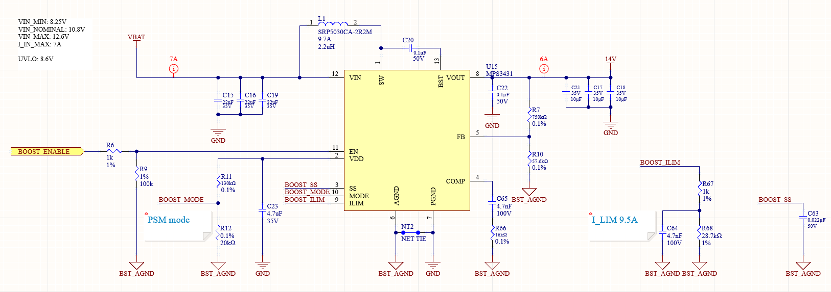
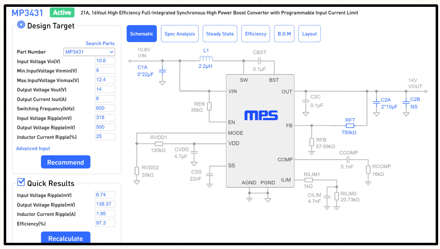
We are using the MP3431 to supply the voltage for an Hbridge which is driving a purely resistive load of ~9 ohms at 25 kHz. The input voltage is a battery pack with a nominal voltage of 10.8V and and output voltage of 14V. Here is the circuit we’ve built on our first prototype PCB:
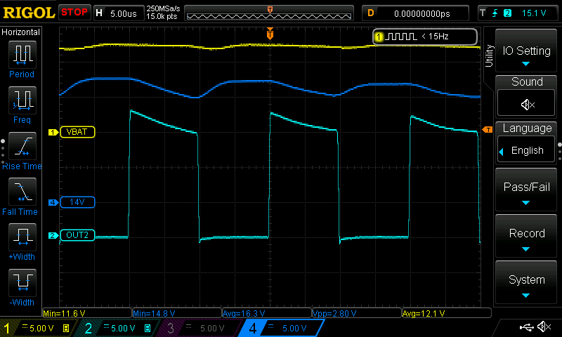
We are seeing large drops in the output voltage when the load is switched on, roughly ~2.8V of variation. This is causing problems since we are trying to precisely control the amount of power delivered to the load. Here is a scope capture showing the step response:
Is this just beyond the capability of the MP3431 to handle a step response like this?
Are there any design issues with the circuit?
Is there anything we should try with the compensation network to improve the step response?
We are very space constrained and had to compromise on the amount of output capacitance so we are expecting less than ideal output voltage ripple but even this is far beyond the estimate from the web design tool. Any help is appreciated, thanks!
It is the stability problem. Can you try to test the load transient performance and the sw node waveform? For the load transient test, you can test the load from 10% to 90% of your maximum load with any slew rate. I want to see the undershoot and overshoot performance.
I’m working with Mike on this product, and I’ll chime in.
The MP3431 datasheet gives us equations for the frequency of the pole, frequency of the zero, and frequency of the right-half-plane zero. However, I don’t know how to translate those numbers into a gain vs frequency graph to actually determine the cross-over frequency and gain/phase margin. Can you elaborate on how to determine those values? Any chance there’s an LTSpice symbol for the MP3431?
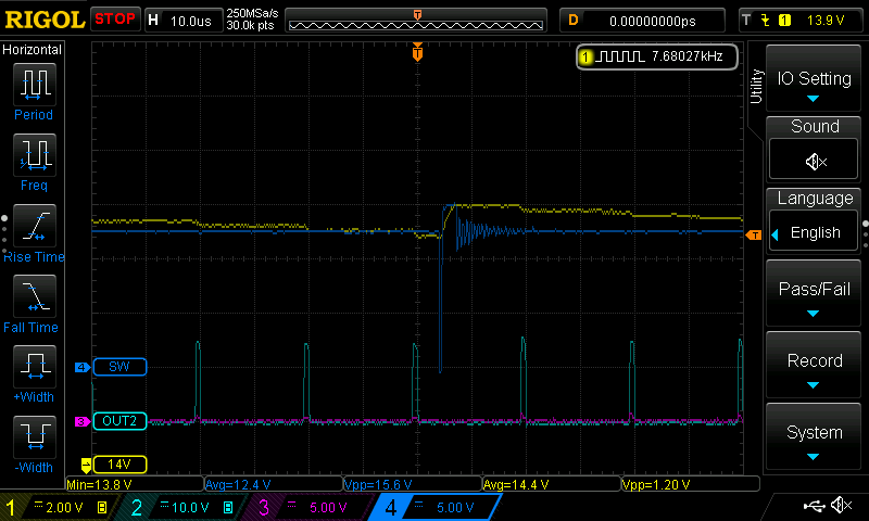
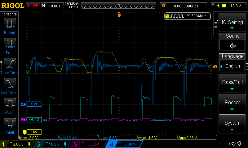
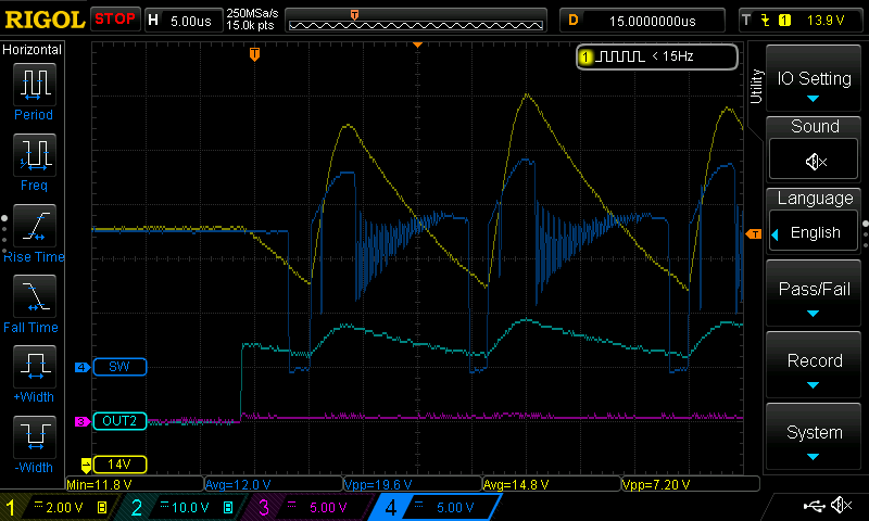
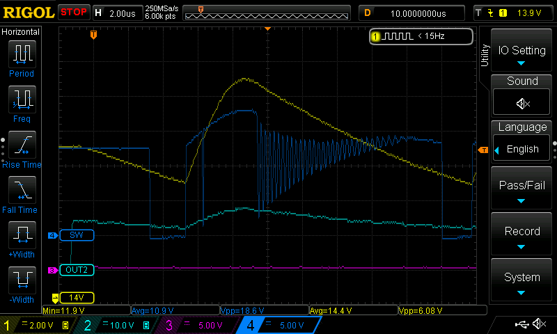
@Fox.FAE Here’s scope captures showing the SW net (CH4), the 14V output net (CH1), and the voltage across the 9 ohm load (CH2) at 10%, 50% and 90% duty cycle. Let me know your thoughts and if you have any suggestions on things we can try. Thanks!
We don’t have the LTSpice model. But for the GM/PM/BM of the circuit, we usually do the hardware tests to get the values. Do you have a bode plot test equipment such as Bode100? I can help you do the bode plot test and get the values you want.
From the SW waveforms, we can find that it is really noisy. Can you share the Layout file with me? I can help you do a layout review and we can probably find the problem.
I emailed you the files. This is a six layer board with the MP3431 on the bottom layer (layer 6). There is a ground plane on layers 2 and 5. We route some signals on the top layer (layer 1).
@Fox.FAE
Thanks for the tip regarding the Bode100. I don’t have one and it costs $6700 so I don’t think I’ll be purchasing one
Do you know of any less expensive / hobbiest level tools to do that same thing? Or shall I instead go down the path of transient load response testing?
Is this a service MPS can do for us if we ship you hardware?
We have a video for the stability analysis. You can watch the video and get the PM and BW with load transient tests. If you have any questions please let me know.
We do provide testing service for you. If you want us to do some tests for you, please submit the ticket. A member from the MPS NOW team will contact you within 24–36 hours about this request.