I want to do a high lumens Flash light product (5000lm output).
we will use a battery (21700) for input device, the battery voltage 3.7Vdc.
The output loadings are use LEDs (6V/5A — for 1set), our loadings will use 2 sets LEDs and 2 sets MP3431.
I know MP3431 is CV driver IC. DO you know how to modify the circuity to do CC mode?
Welcome to our community. I am researching the correct solution for you to do CC mode. Since you have two sets, can you please confirm that the total LED current will 10A at 6V which total power of 60W when both Sets are power ON at the same time?
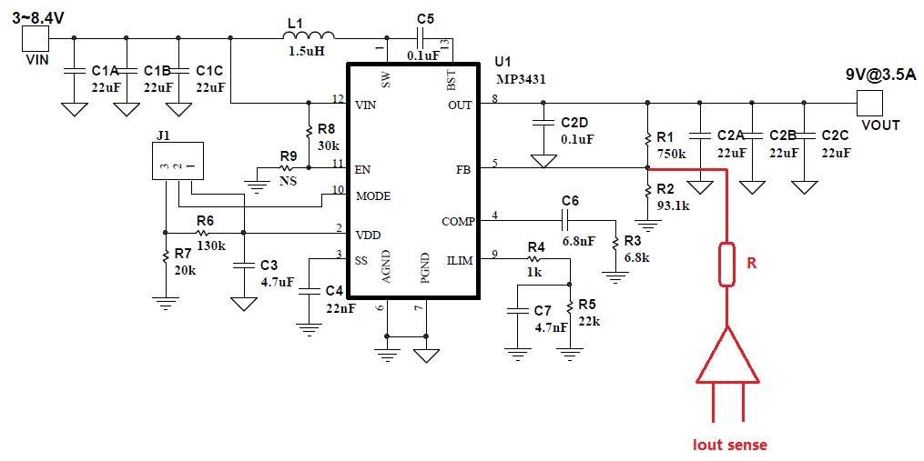
Awesome. In that case you can sense the output current and then feedback to the FB node as below schematic. FB resistor divider from Vo to FB pin is still needed to set the OVP threshold of LED power. This circuit can work in CC/CV mode.
Hi,
Instead of creating a new thread I found this one, which is what I am looking for. I am using a single MP3429 instead of the MP3431 but for my purposes they are basically the same.
ACDCguy (or other MPS engineer), if I may ask, could you clarify a little more on the Iout sense part in your suggested solution? I am a too much of a beginner to know exactly what it your solution is. The red triangle you added, is it a OP-AMP, current sense amplifier or something else? Would it be too much to ask for a more detailed schematic of your solution? And also, how would I calculate the resistor you have added above it?
I have been looking for specific LED drivers with CC regulation and boost topology but I have not found any device that comes close to the MP3429/31 output capacity. I have designed PCB around the MP3429 which works except that and am having difficulties implementing CC instead of CV. Any help will be appreciated.
Welcome to our community !
The MP3429 has an internal reference of 1V. So the MP3429 will try to keep the voltage across R2 (93.1K) at 1V. The red triangle is an OPAMP wired as a DC differential amplifier. The Input to this is the voltage across the current sense resistor that is in the Ground wire between the Load and the Power supply. For now assume the Current through R1(750K) is small enough to be ignored. So the current in R2 is the same as the current on the red resistor labelled R. If the control loop maintains 1V across R2 that means the current in R2 is 10.7uA while in regulation. This 10.7uA also flows through the red resistor R. Lets assume R is 100K. This will create a drop of 1.07V across the red resistor R. So the Output of the Differential amplifier stage is at 1+1.07=2.07V. Let’s assume that the differential amplifier stage has a gain of 20. This means that the voltage across the current sense resistor is approximately 103.5 mV. If you want to regulate the output current at 1A then a 103 milliohms current sense resistor will create the 103.5mV needed for 1A CC regulation. If you want to regulate at 10A then you will need a 10.3 milliohm current sense resistor to create the 2.07V at the output o the differential amplifier stage. You can play with the gain of the differential amplifier and the current sense resistor value to get the CC regulation point. I hope this helps.
hello
I want to boost a single lithium battery to 12V, but I want to have high efficiency when the battery is below 3.4V, so can I use an external power supply to power VIN?
I am sorry but can you please share the Output load current ? Assuming it is between 300mA- 2A for the 12V output, then MP3437 is the best choice for efficiency. The next option is MP1541. The MP3437 has >95% efficiency at 1A when input is 3.4V. The MP1541 has > 85% efficiency when the input is 3.4V for load current between 50-150mA.
Thank you very much for the detailed description! By reading it a few times and internet searching on differential amplifiers I have grasped the basic concept of it, at least enough to start practical testing.