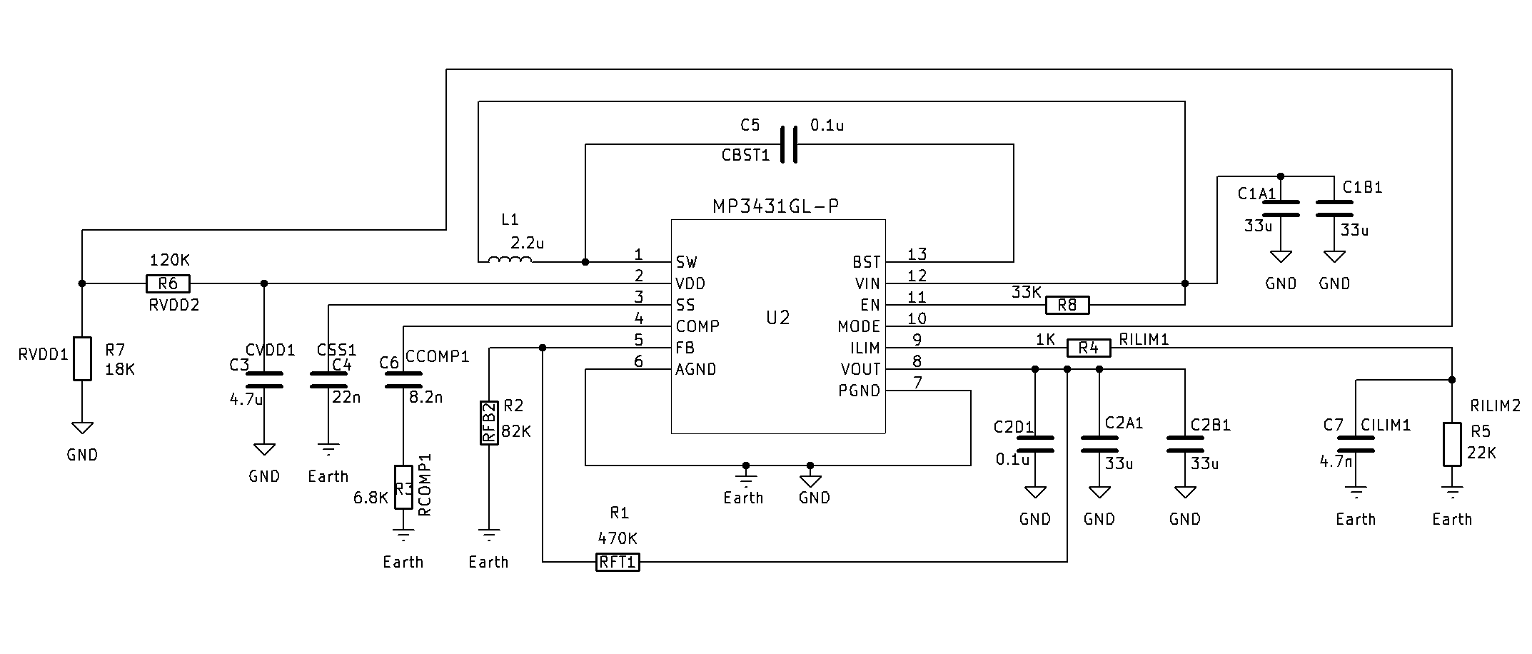
I am trying do get basic functionality of this IC following pdf datasheet and online Designer tool as calculator, but looks like it cant maintain constant voltage and ~1V at FB pin. FB pin keeps at ~1V only when there is no load. When connect any load, LED, or some resistor of ~4 Ohms, output voltage drops and stays there, and FB pin voltage drops, of course. For example, in my case with this values (on picture) of components, I get, no load output voltage ~6.8V and FB pin is ~1V; when connect 3.9 Ohm resistor as a load, output drops to 3,6V. Input is Li Ion battery, voltage ~4V. Should not this IC keeps output voltage constant (as can be seen in MPSmart simulator for MP3429 spice model)? Input and output capacitors are tantal.
Someone already answered me on other topic which was closed for some reason.
And now, after a few months of waiting for right components, the situations is the same,
I put R1=470K and R2=91K to get around 6,2V, and I get it without load. When I put some load like small value resistor, few ohms, or LED (which I intended this power supply for) I get ~5,47V , and no matter what voltage divider, I put some other resistors to get ~6,8V no load, and with LED, still 5,47V.
Inductor now is: 1u5 Isat=22A , input and output tantalum capacitor changed for cheramic, but situations still the same.
For no load and lite load (larger resistors) it maintaines constant voltage.
As this topic did not have any replies for more than a month, it got closed automatically. No worries, I can take a look at this issue from my end and will get back to you on this.
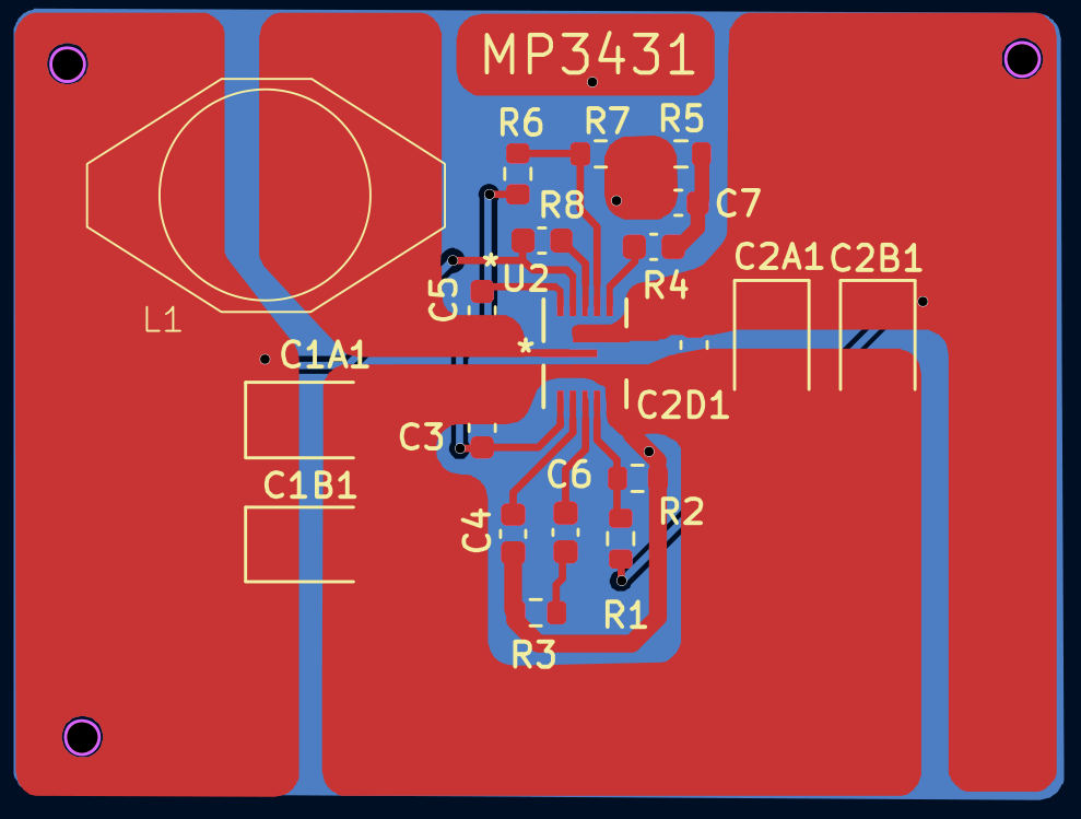
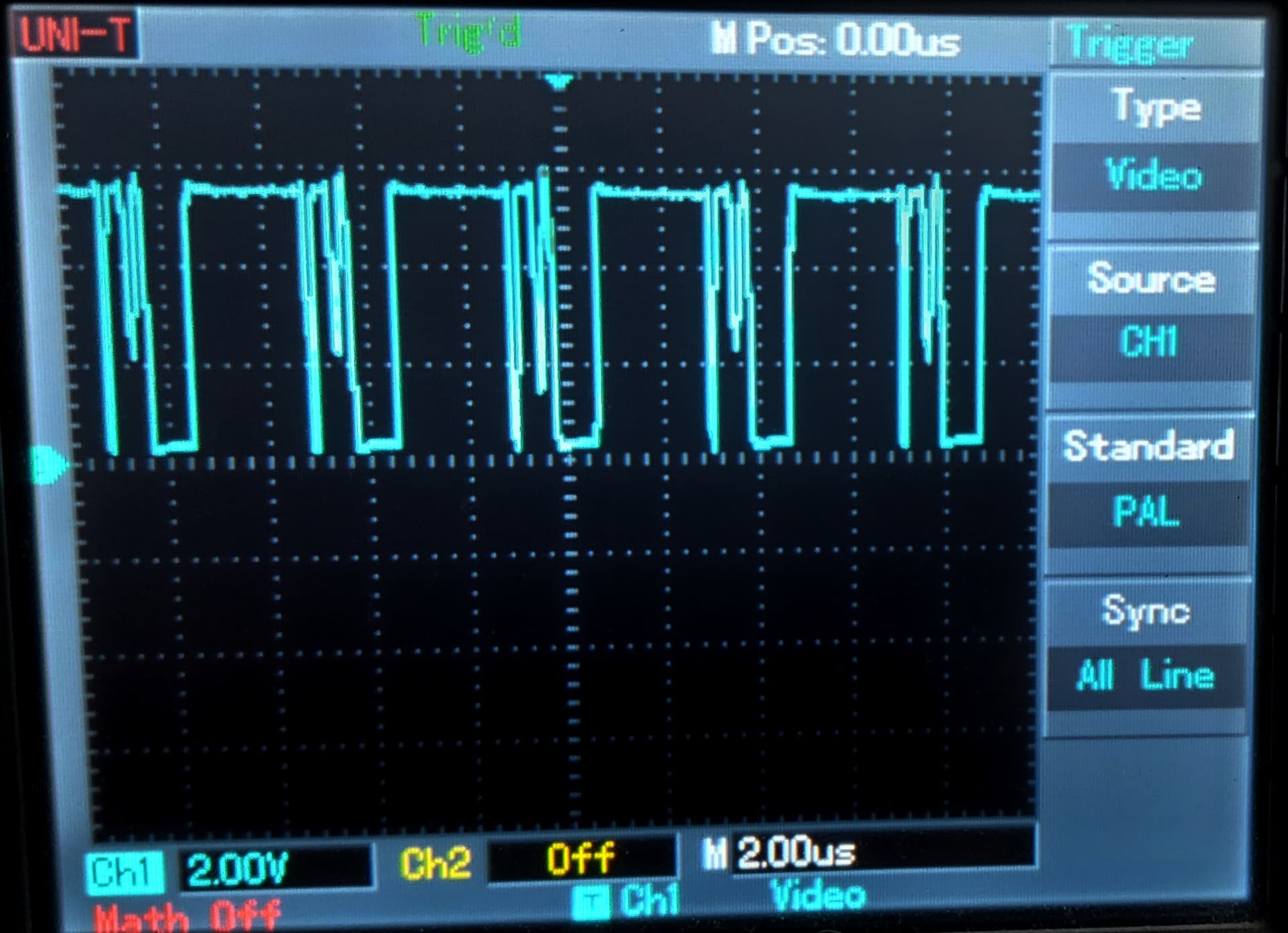
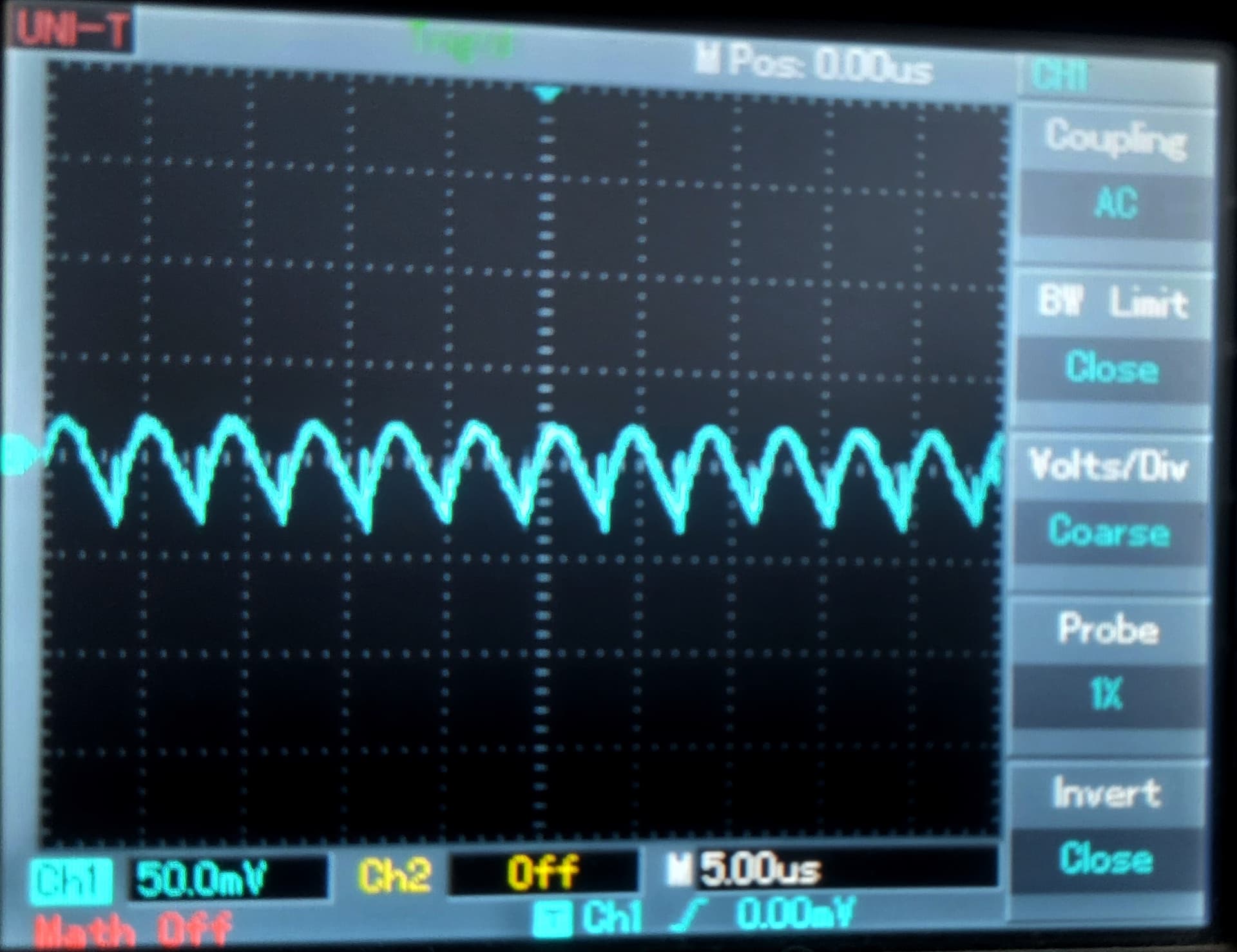
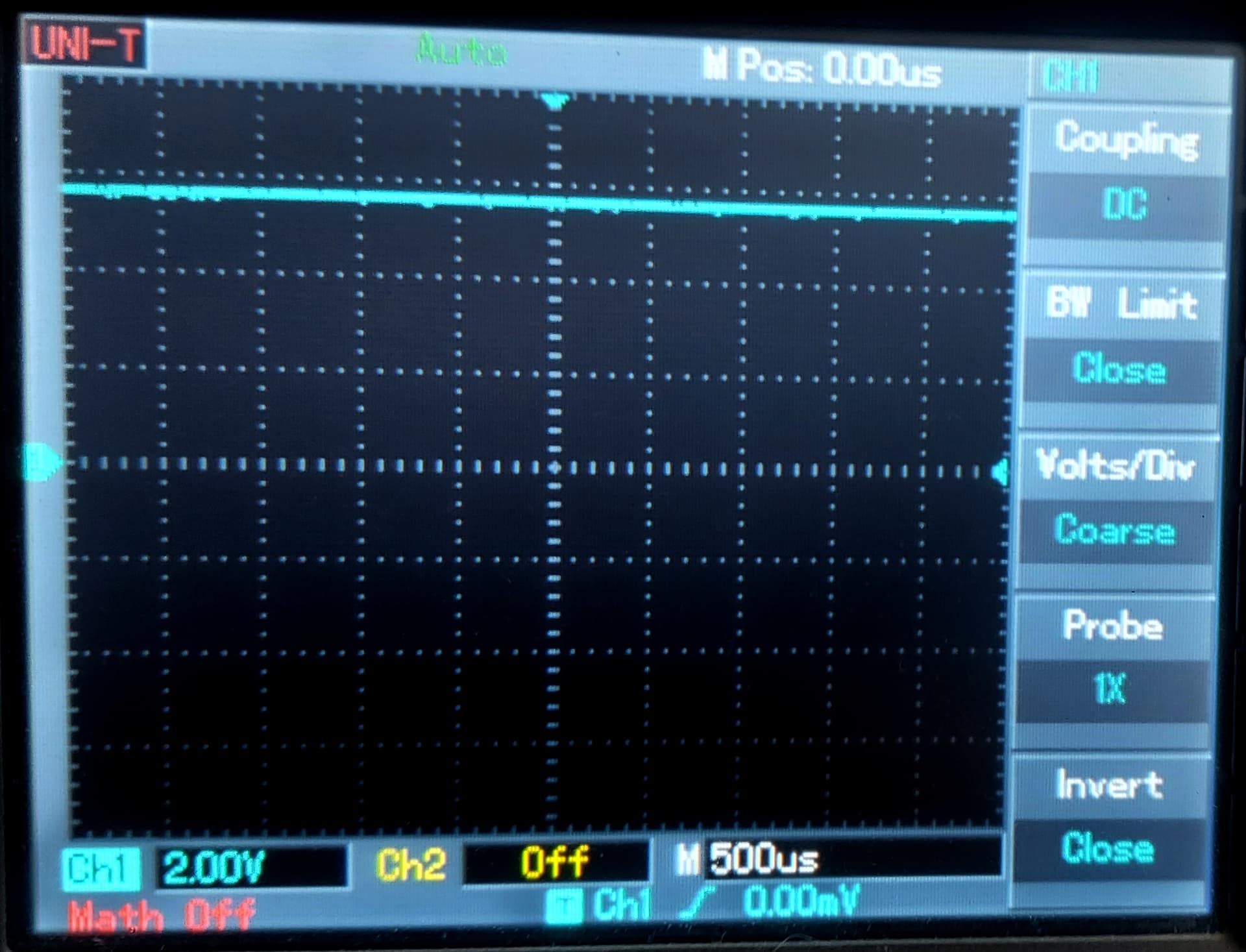
Output voltage typically should be constant, for this I will review your schematic and layout as well again. In the meantime, may I know how much load current are you expecting to draw from your LEDs with an output voltage of 6.8V? Did you capture any waveforms from your oscilloscope to share such as Output voltage, inductor current, Switch node voltage?
And I cant watch current waveform with my oscilloscope, I dont have some current probe. I probably should create some shunt resistor to convert current to voltage or something like that.
And I am using some li ion battery IMR26650, which can draw 15Amps constantly. But for example, when I try some NCR18650 batteries, for some reason I get very fast blinkig led output, and sometimes steady… Very unstable.
I see your switch node is not stabilized, may I know what inductor (still 1.5uH? or 2.2uH?) and the load setting you used for this capture, is this at no load or maximum load?
This is with 2.2uH at the moment. I tried also with 1.5uH (Isat=23A) before 2.2uH (Isat=18A) but situation is the same. I also used inductor 2.2uH (Isat=6.5A) a months ago when I posted first thread, but in that time, situation was the same; could not get constant voltage.
And those images was recorded with LED load.
I use LED as load, and I measure 0.45A throu LED at ~5.5V (should be 6.8).