Hi everyone,
I would like to calculate the values for the MP3429 compensation network.
Unfortunately I don’t know much about control theory for choosing the right frequency and the DC/DC Designer Online tool does not support this chip yet.
Could anyone please give me a hint how to choose F_P1, F_Z1 and F_RHPZ.
Best regards.
Hi clement.kammler,
The MP3429 has some equations on how to calculate for the compensation network in equations (10), (11), (12) on page 19 of the datasheet. However, unless you are using significantly strenuous transients, you can get away with the default 6.8nF cap and 6.8kOhm resistor network. I understand the poles and zeros may be confusing on what to choose for a stable system. In most scenarios, the default values are fine but if you notice a lack of stability you can start tweaking the COMP network.
Thanks,
Brendan
Hi Brendan,
thank you so much for your answer.
Unfortunately I am expecting big current spikes.
The MP3429 is powered by 5.7V Super caps and has the task of buffering short main supply interruptions of up to several 100ms.
The main supply normally is around 16-18V and the MP3429 should provide 14V/1A (or a bit more) and is separated by a diode from the main supply.
So I am expecting current spikes from <1mA idle to about 0.5A, 0.7A or 1.0A.
Best regards
Clément
Do you know the slew rate of the transients? I would still expect the default COMP values to handle this situation given the current spikes are only 1A max.
Thanks,
Brendan
Hi Brendan,
actually, I can’t really tell which slew rates to expect.
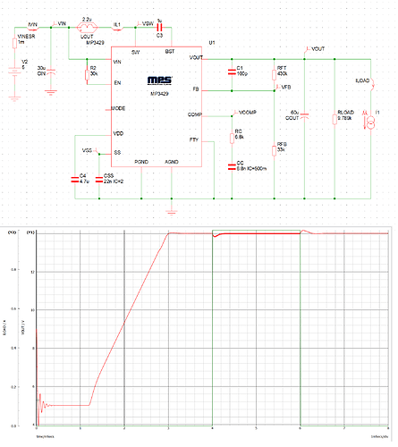
But I tried a simulation with MPSmart with my values and got these results.
The added feed forward cap helped to flatten the voltage spikes during current transients.
The slew rate in the simulation is 1A/10us.
I think I am happy with these results.
Or do you have further optimisation hints?
Best regards
Clément
Correct, the feedforward cap is a great way to improve transient performance and is often one of our first recommendations. That slew rate is pretty slow so I would expect good transient results. If you are happy with this simulation and you think this will reflect your actual load conditions, then I think the next step would be to try testing this on an evaluation board or your own prototype.
Thanks,
Brendan
Thank you verry much for your support.
I will try the circuit with these values.
Greetings,
Clément
