Greetings all,
I am working on a boost converter to go from from ~12v to 19v and deliver around 5A.
I am working with the evaluation board as a reference. I have been able to modify the evauation board to meet my requirements and it seems to do the job resonably well.
When it comes to replicating it I am not faring so well. The switching mosfet gets very hot very fast.
(what would be Q2 on the evaluation board)
I am using a RS1E280BN.
To try to narrow it down, I removed the part that was in the location of Q2 on the evauation board and installed a RS1E280BN. There was no quantifiable change with the evauation board, so I don’t think it’s the MOSFET selection. (which right now is somewhat difficult)
The MP3428A itself doesn’t get unreasonably warm remaining under 60c - and some of that I suspect is from Q2 as they are fairly close.
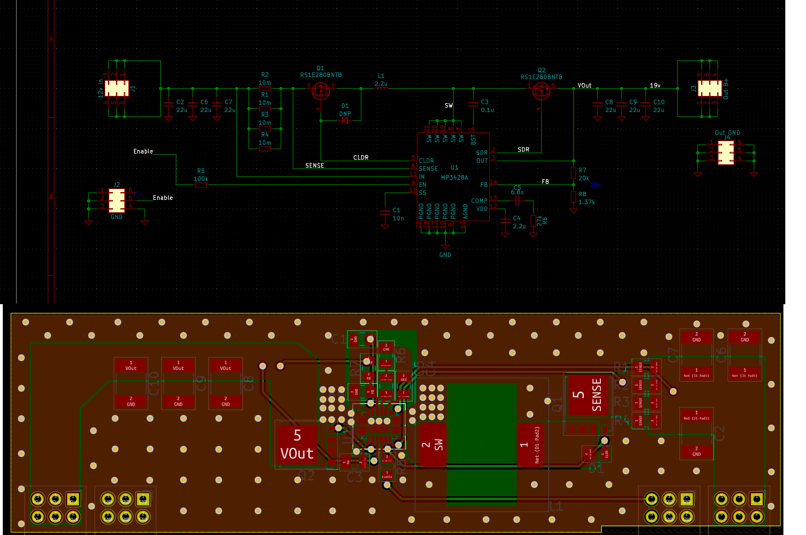
Layout is idential to the one in the datasheet.
I tried swapping some components between my board and the evaluation board like the inductor, but that made no difference.
Simply put, it works on the evauation board but when I migrate it to mine, it does not. Does anyone have any suggestions?
Hi mark19960,
Thanks for your question.
I’ll need some more information.
Can you provide the schematic of your board?
How is the board layout compared to the EVB? (Please provide a layout pdf if possible) Did you try swapping the MOSFET from the MP3428A EVB to your board? If so, how did it respond?
Component placement and trace width could be a factor in the MOSFET getting very hot.
Regards,
Cindy
Hi Cindy,
Yes I did try swapping the MOSFET across boards. No change.
The evaluation board worked fine, mine got as hot as the sun 
It would only let me attach one image and I could not work out how to upload a PDF, so here are both in one image… sort of cheating a little i guess
The relatively empty area to the left where C8-10 are, we planned on adding additional filtering if we needed it.
Hi,
So I don’t see any immediate discrepancies in your layout and schematic. But there could be a difference in board layers and other PCB layout factors
It seems the FET might be getting extremely hot because your output power is nearing 100Watts. Could you measure the temperature of the boost converter and FET?
Is the concern with the high temperature because the part will shutoff or something else?
Are you getting the desired output on your PCB and the EVB?
Also, reading the EVB datasheet, it looks like the board is designed to only handle 3 to 10Vin. Whereas it seems you’re inputting in 12V.
Did you make modifications to handle this change?
Thanks,
Cindy
I did change the inductor on the evaluation board to account for the higher current.
As to the rest - no, because none of the parts in the bill of materials would have been affected by the 2 volt increase, and on the output side it was closer, but still everything was good up to 25v.
This is only a 2 layer board.
The MP3428A hits around 150F.
The FET? I shut it down when it passed 150C. It would have happily gone into runaway at the rate it was climbing. Temps measured with a thermocouple and a Standford Research SR630.
This has to be some weird layout problem. I will probably try to copy the evaluation board layout more closely and try again unless you have some suffestions.
Thank you Cindy.
Can you state whether you were able to get the desired output on your board and the EVB?
Also, did you change R2 to account for the output voltage?
Cindy