I used the evaluation board for the MP3320B to test exactly what will end up on my schematic. MP3320B Eval
In my application, a 3.3 volt VIN, I do not need to step up Out > Vin.
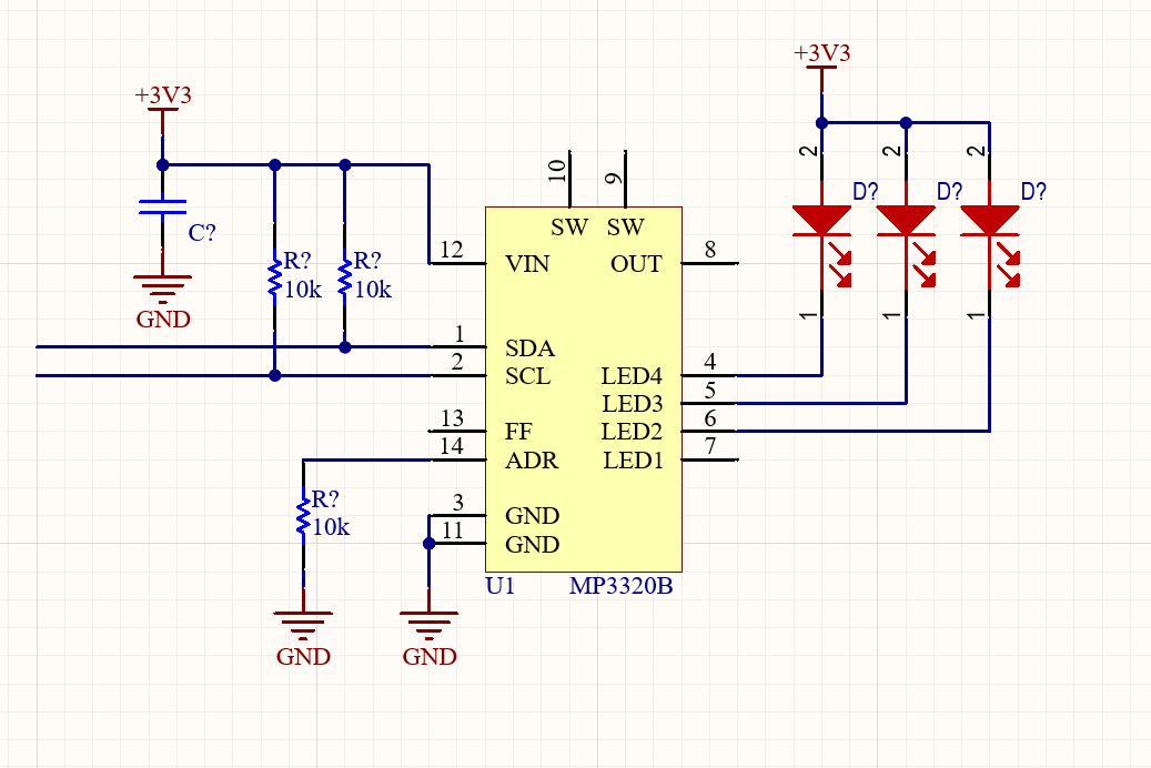
I made modifications to the eval board and want to confirm there wont be any issues in this configuration.
Changes:
Removed Vin input resistor (R1)
question: what is this resistor used for? Is it necessary? I dont see the reasoning for it in application notes
Removed the inductor
question: Do I lose any functionality for the MP3320B other than OUT > VIN
Out left disconnected
question: Is it okay to completely disregard the OUT terminal? Or does OUT have to be connected to VIN even if SW is left floating?
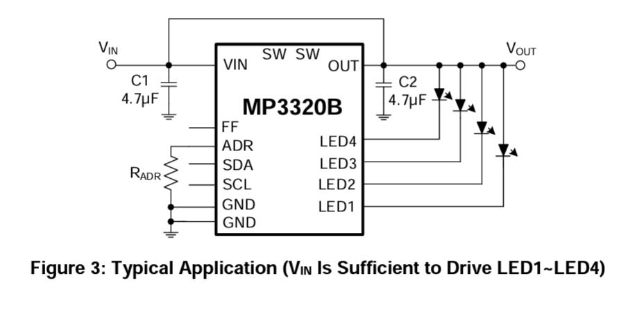
That particular application is for when Vin is sufficient to drive the LEDs. So you are just exploiting the internal current sinks to regulate current. If Vin is insufficient then your first have to boost it.
Input filters on the power? Who knows I think often they are there for decoration, sometimes they can even cause problems. Somebody at MPS who spends all day thinking about circuits thought it was a good idea. Probably totally OK to not use it.
VIN has to be connected to OUT through an inductor in case you need to boost. But the MPS rep told me to connect OUT to VIN even if I am not boosting. I was asking why in that particular case I would have to.
You have to look at some stuff. What is the minimum Vin you want the circuit to work at?
What is the maximum Vled? If Vled is lower than Vin ( save a little for the chip as well) then you connect Vout to Vin as boosting is not required.
I am asking why I even bother connecting the OUT pin to the LED cathode if I am just going to drive them from VDD/VIN. Why connect out? Does it aid in some current control feedback having OUT connected to VIN?
Oh I see, good question, no idea, maybe the current control circuits need to see voltage on Vout before they enable? I would say in principle you shouldn’t have to but there might be some detail that will get you. Are traces that expensive these days?
I tried OUT totally disconnected on the eval board for the mp3320b and I was still able to set different currents. Who knows, maybe there is some feature that may not work as well without OUT connected. Like you said, there might be some detail that will get me. I may as well just connect it. Thanks for the help!
@MPSNow_Saurabh if I am not boosting (VIN enough to drive LED), can I power the LEDs from VIN/VDD and leave SW and OUT floating? As shown in the initial schematic I posted.
Does OUT provide feedback to internals or anything like that which would be a reason for leaving it connected to VIN?
Good idea, I was just going to suggest that as a way to save an inductor in the event that you had a higher voltage available. One thing to check for would be if there is a diode between out and in ie. would 5V on the LED pin flow through the IC and out the Vin pin? You might need to tie OUT to the high voltage as well in that case