I’m using an STM32L431 to control two MP3320B 4-channel LED drivers over I²C. I’ve noticed a strange behavior that depends on whether the debugger is connected.
Hi justina,
Can you elaborate more on the I2C/debugger connection here?
Do you have any waveforms or schematic to share with us that can better help us to understand the issue?
Regards,
Adhish
I am sorry, my original post was cut off. Here are more details:
Setup:
- All LED channels are initialized to 0 duty using DPWM registers.
- PRO_MD initially set to 0x1C (0001 1100) to disable short protection during initialization.
- Channels enabled via CHN_SET until all 4 are active.
- BLK_MD initialized to enable the device.
- After initialization, PRO_MD set to 0x5C (fault bits enabled, channels should stay on even if a fault occurs).
Observations:
- With debugger connected via SWD (SWDIO, SWCLK, optional SWO, and NRST using a TAG-Connect cable), all channels run fine and no faults seem to be reported.
- Without the debugger connected, after power-up, I consistently get short-channel faults on some channels (usually CH2) of both drivers, even though LEDs are properly connected and functional.
- My configurations in both MP3320B looks like this (read in runtime):
blk_md: 0x08 (0000 1000)
boost_md: 0x24 (0010 0100)
chn_set: 0x0F (0000 1111)
stepup_down: 0x11 (0001 0001)
iled_fpwm: 0x10 (0001 0000)
iled_fblk: 0x20 (0010 0000)
dutyblk: 0x03 (0000 0011)
blk_times: 0x00 (0000 0000)
pro_md: 0x5C (0101 1100)
fau_state: 0x60 (0110 0000)
Additional Observation with USB Hub:
I use a UGREEN USB hub to get more ports on my computer. The hub has two USB-A inputs to the computer and four device ports.
When both the debugger and USB-CAN adapter are connected through the hub, everything works fine — no faults.
When the debugger is unplugged mid-run, the board continues running and no faults appear.
Even after full power cycling with only the USB-to-CAN adapter still connected to the hub and no debugger physically connected, no faults are detected.
However, if I connect the USB-CAN adapter directly to the computer (bypassing the hub), the faults appear again immediately.
Power Supply Observation:
I am powering the board from a bench PSU set to 5 V with a 0.2 A current limit.
The board’s current draw is low (~0.01-0.02 A before initialization, ~0.04 A after initialization, slightly higher once CAN and MP3320B are active).
Even though the current is well below the PSU limit, some RGB channels report short faults during power-up.
Using a normal USB-CAN adapter or a PSU without a strict current limit, these faults do not appear.
What I Tried:
- Verified initialization is done and both MP3320B are functional.
- Ensured DPWM and CHN_SET values are correctly written.
- Checked CAN messages to confirm repeated fault reporting.
Question:
Could this behavior indicate:
- A timing or initialization issue in my STM32 code?
- A hardware problem, such as wiring or I2C signal integrity?
Any insight or suggestions for debugging this issue is appreciated.
Thanks in advance!
P.S. Initialization code:
static const MP3320B_Reg dpwm_ch_low = { MP3320B_DPWM_CH1_1, MP3320B_DPWM_CH2_1,MP3320B_DPWM_CH3_1, MP3320B_DPWM_CH4_1};
static const MP3320B_Reg dpwm_ch_high = { MP3320B_DPWM_CH1_2, MP3320B_DPWM_CH2_2,MP3320B_DPWM_CH3_2, MP3320B_DPWM_CH4_2};
uint8_t MP3320B_WriteReg(MP3320B_t *device, MP3320B_Reg reg, uint8_t data) {uint8_t addr = device->addr;I2C_TypeDef *i2cx = device->I2Cx;
bool is_transmitted = I2Cx_WriteData(i2cx, addr, reg, 1, &data, 1); if (!is_transmitted) { return 0; } return 1;
}
uint8_t MP3320B_SetDPWM_CHx(MP3320B_t *device, uint8_t led_duty, uint8_t led_channel_nr) {if (led_channel_nr < 1 || led_channel_nr > 4) return 0;
uint16_t duty_10bit = ConvertDutyTo_10bit(led_duty); uint8_t buff[2] = { (duty_10bit >> 3) & 0xFF, duty_10bit & 0x07}; uint8_t ch = led_channel_nr - 1; uint8_t status = 0; status |= MP3320B_WriteReg(device, dpwm_ch_low[ch], buff[1]); status |= MP3320B_WriteReg(device, dpwm_ch_high[ch], buff[0]); return status;
}
uint8_t MP3320B_Init(MP3320B_t *device) {if (!MP3320B_WriteReg(device, MP3320B_BLK_MD, MP3320B_BLK_MD_EN)) {return 0;}
return 1;
}
/*******************************************************************/
// writing to DPWM registers (addresses 14,21) setting all channels duty to 0 MP3320B_SetDPWM_CHx(&mp3320b_1, 0, CH_RED); // MP3320B_DPWM_CH2 MP3320B_SetDPWM_CHx(&mp3320b_2, 0, CH_RED); // MP3320B_DPWM_CH2
MP3320B_SetDPWM_CHx(&mp3320b_1, 0, CH_GREEN); // MP3320B_DPWM_CH3 MP3320B_SetDPWM_CHx(&mp3320b_2, 0, CH_GREEN); // MP3320B_DPWM_CH3
MP3320B_SetDPWM_CHx(&mp3320b_1, 0, CH_BLUE); // MP3320B_DPWM_CH1 MP3320B_SetDPWM_CHx(&mp3320b_2, 0, CH_BLUE); // MP3320B_DPWM_CH1
MP3320B_SetDPWM_CHx(&mp3320b_1, 0, CH_WHITE); // MP3320B_DPWM_CH4 MP3320B_SetDPWM_CHx(&mp3320b_2, 0, CH_WHITE); // MP3320B_DPWM_CH4
// writing 0001 1100 to PRO_MD registers to fully disable short protection actionsMP3320B_WriteReg(&mp3320b_1, MP3320B_PRO_MD, 28);MP3320B_WriteReg(&mp3320b_2, MP3320B_PRO_MD, 28);
uint8_t all_channels_set = 0;
uint8_t retries = 0;

// waiting for all 4 channels to be set in CHN_SET register which always happen successfully
while (all_channels_set < 15 && retries < 10) {
    MP3320B_WriteReg(&mp3320b_1, MP3320B_CHN_SET, 15);
    MP3320B_ReadReg(&mp3320b_1, MP3320B_CHN_SET, &all_channels_set);
    retries++;
}
all_channels_set = 0; retries = 0;

while (all_channels_set < 15 && retries < 10) {
    MP3320B_WriteReg(&mp3320b_2, MP3320B_CHN_SET, 15);
    MP3320B_ReadReg(&mp3320b_2, MP3320B_CHN_SET, &all_channels_set);
    retries++;
}

// finally initializing by writing to BLK_MD register setting (1 << 3) (EN) bit to 1
MP3320B_Init(&mp3320b_1);
MP3320B_Init(&mp3320b_2);

// after that writing 0101 1100 to PRO_MD to enable fault signaling without disabling faulty channels

MP3320B_WriteReg(&mp3320b_1, MP3320B_PRO_MD, 92);
MP3320B_WriteReg(&mp3320b_2, MP3320B_PRO_MD, 92);
Hi Justina,
Appreciate sending the detailed observation.
It looks like it could be a cable/wiring issue and probably one of your LED string is shorted more than the threshold value time it can handle. As per our datasheet, please refer to the below note:
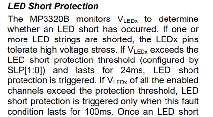

Double check your LED string connections when you are changing your ports, debugger and CAN adapter.
Regards,
Adhish