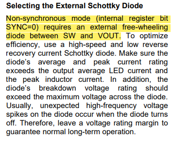
Implemented the circuit as from the datasheet (without the free wheeling diode) but with 150R and the capacitor in series. Worked great with 9 LEDS in series using default I2C with DIMS=0
when using NON SYNC (0) mode and PWM (DIMS=1) mode and without the diode (no any changes we made, just register settings change) the backlight suddenly stopped. Even going back to DIMS=0, the output voltage stays around 3 to 5V (was about 19V before) and it seems the circuit is demanding lot of power (like a short) when setting EN=1 in register 0 as the LED on the 3V3 power dims when setting EN=1. After power on/off nothing resolved the issue.
What could be cause, it would be a bit surprising if the MP3309C went bad by a software setting change. Could setting non-ASYNC with PWM (DIMS=1) mode w/o the diode damage the MP3309C
Replaced the 22uH 0.68A Inductor and noticed it becomes very hot so far that it becomes not touchable with 9 LED is series (which don’t light up). Even the external linear regulator feeding the 3.3V/5V to the circuit becomes very hot in this case.
Though, when using only 2-5 LEDS in series the 2~5 LEDs do light up and the external regulator and inductor immediately cools down. This is with reg 0 is set to 0x84 an d reg 1 to 0x28. It seems there is a kind of short or low impedance situations but the circuit seems fine. (as said only after the register setting change this happened)
note: corrected the title
note: the backlight LEDs work fine with another board usinG MP3302
note: FB resistor is 10ohms and resistor on Freq is 100K
P.S: in NON-ASYNC mode should the resistor and cap between OUT and SW be removed ?
Hi Debug, What could be cause, it would be a bit surprising if the MP3309C went bad by a software setting change. Could setting non-ASYNC with PWM (DIMS=1) mode w/o the diode damage the MP3309C
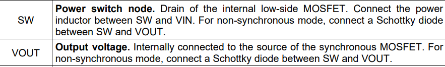
It would damage the device if a diode is not added. Please refer to the note on page 11
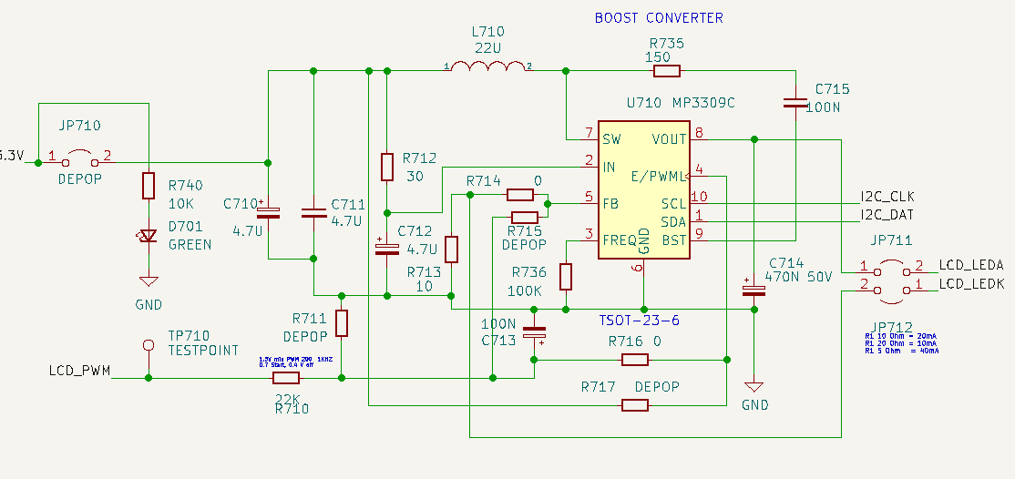
Can you please provide the schematic for us to review so that we can have more understanding of what problem are you seeing?
Thanks, the manual did not state that if omitting it, it would fail the IC in NON-SYNC mode. Please confirm ? If so, that explains it and we’ll replace it and add the diode to prevent this from happening again .
Schematic needs a bit of cleanup . its was a quick draw and a mix of the datasheet and demo board. Note there is a mistake in the diagram , pin 3/4 swapped. Fixed before testing. R717 = 100K.
Yes for non-synchronous mode, a diode is required as mentioned before. This should fix the issue.
Schematic looks ok as per your comments. Regarding the inductor getting hot, what is your magnetics calculations for inductor, what is the DCR value of it? And what type of inductor is it? Wire wound, shielded , molded ? These can be one of the factors for the device to be hot due to the core and ac losses associated with it.
I would recommend looking at the inductor current waveform on the scope and see if exceeds the load current for a particular time period.
If the inductor is operated at or over its saturation current rating, it will lose its inductive qualities as well as generate excessive heat as a result of core losses.
I agree on the shorting somewhere, but ensure if the inductor is properly soldered or not, if there insufficient airflow, it may fail to disperse heat effectively, resulting in overheating.
Thank you very much . I understand adding the diode in non-sync mode is needed. The question was without the diode in non-sync mode, would/should/could that damage the mp3309c so that it does not work in sync mode anymore ? (our situation) if not, we need to check the board what else might be wrong with it. Is there anything else we can test if the mp3309c is (partially) defect or not ? (replacing this part by hand is a bit of a hassle). The inductor is SWPA4020S220MT Shielded Drum Core, Wirewound Inductor (DCR 0.455, I=620mA. Would Born DSS24 (no spec for reverse recovery time) be usable for the diode (or even DSS14) ? The total current demand is in thelow few hundereds of mA. Vmax 20V
Yes, it may have damaged the IC internally when you were operating in non-synchronous/asynchronous mode without the diode at first when SYNC bit=0.
Thus, switching back to synchronous mode won’t work properly.
PIN functions clearly mention the use of diode for non-synchronous/asynchronous mode of operation.
Now, if you want to check the IC in synchronous mode, but you are not seeing the expected output try observing the switch node voltage and the inductor current waveform on the scope.
For the inductor, rated current of 0.62A looks bit low & DCR is high, I would recommend using a lower inductor value which has high rated current. For example, something like this part A921CY-180M=P3
Lastly, for the schottky diode selection, both DSS parts are a good selection depending on your load current requirements. The trade off will be for the efficiency here where DSS24 has a higher leakage current & forward voltage compared to the DSS14.
If you are sure that your calculations for maximum value of load current and inductor peak current will be under 1A, then going with DSS14 makes sense. Otherwise, DSS24 is good for a safer margin.
Many thanks, I have been using this inductor and diode with MPS3302 with many LCDs with much success. The current board does not support large coils, but next layout I allow to match the coil with max current of the MP3309. Right now I use 9 standard 1.2V LEDS ,the current should be very low. Some options quickly available are SWPA4030S150MT / S180MT 18uH 1.5A DCR 0.24/0.26R for higher power and lower DCR.
Added the DSS24 between SW and VOUT diode and tested in non-sync analog and PWM mode and the result is about the same. Only 1 to 4 LEDS to light up. (EN=0 disables them) With more LEDs the 5V>3.3 regulator rail start to power on and shutdown in fast about 100msec cycles and both the MP3309C and regulator become hot. For about a second the output ramps from 3 to around 6V and then shutdown happens. After a while in Non-sync mode it even disables itself (EN=0).
Changing the value of DIMS in analog sync mode just works normally, the intensity of the 3 LEDs in series change according to the DIMS values and the intensity/current is like it working normally . It looks like the MP3309C internal logic is working fine, only the voltage cannot ramp up to beyond about 7V. checked the circuit many times and seems fine. Add a 4th or 5th LED, the LEDs start to flicker and a temperature fault bit comes on. with 4 LEDS and DIMS 31 the linear 9V to 5V and 5V to 3.3V regulators and DIODE get hot beyond touchable after about 5 seconds
with 3 LEDS A/K output is 7V constant
with 4 LEDS A/K output 8V and cycles on and off about every half a second
With 5 LEDS A/K output turns on and immediately turn off and MPS3309C disables itself
The symptoms when using 5 LEDS sometimes occurs using 4 LEDS
The switch node SW voltage in sync mode with 3 LEDS with DIMS 0 = 3.226V, DIMS 1 = 3.206V and
DIMS31 = 3.068V / voltage on FB with DIMS set to 31 is 0.2V, with DIMS around 1 it’s 0.035V
Replaced the input regulator and no difference
P.S: Should C715 and R735 be removed in Non-sync mode ? I have seen some designs w/o R735 as well in sync mode.
P.S: Should the diode be removed in SYNC mode ?
I am still not convinced the MP3309C is defect, since everything seems to function, it could be something else overlooked.
Sorry to hear that it did not work, do you mind sharing waveforms for the input voltage, switch node voltage, inductor current, led current and output voltage?
When you 3 LEDS A/K
What does A/K mean here?
Also, I am not able to clearly understand the comment on the switch node voltage in sync mode related to DIMS 0,1, & 31.
Did you check these DIMS values on the scope? If yes, can you share any scope captures for this?
Should C715 and R735 be removed in Non-sync mode? I have seen some designs w/o R735 as well in sync mode.
The bootstrap resistor (R735) minimizes the peak current offered to the high-side driver, slowing the switch’s turn-on and decreasing the ringing on the switch node. You can try to observe the waveform at the SW node to see the ringing behaviour by removing the resistor or replacing it with 0 ohms. A similar reason for the bootstrap capacitor (C715) when operating the converter in synchronous or asynchronous mode. Removing it won’t solve any issue I guess.
Should the diode be removed in SYNC mode?
Yes, there is no need for a diode in the SYNC mode since it already has a MOSFET internally connected. Refer to the functional block diagram from the datasheet.
Sorry . A/K means the Anode and Cathode output, not the switch node voltage SW. Just using a multimeter between these. We haven not used the scope yet, but will do. Hoped that the comments above could give any clues what is going on.
We were just considering if we could leave the Diode, Cap and Resistor all of them in place for testing in different modes. without having to remove them.
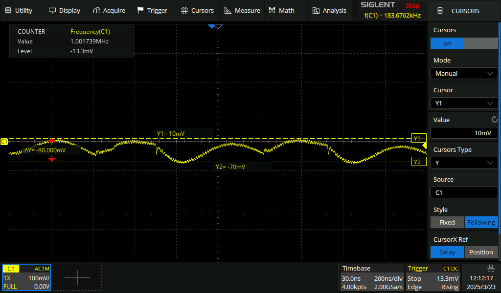
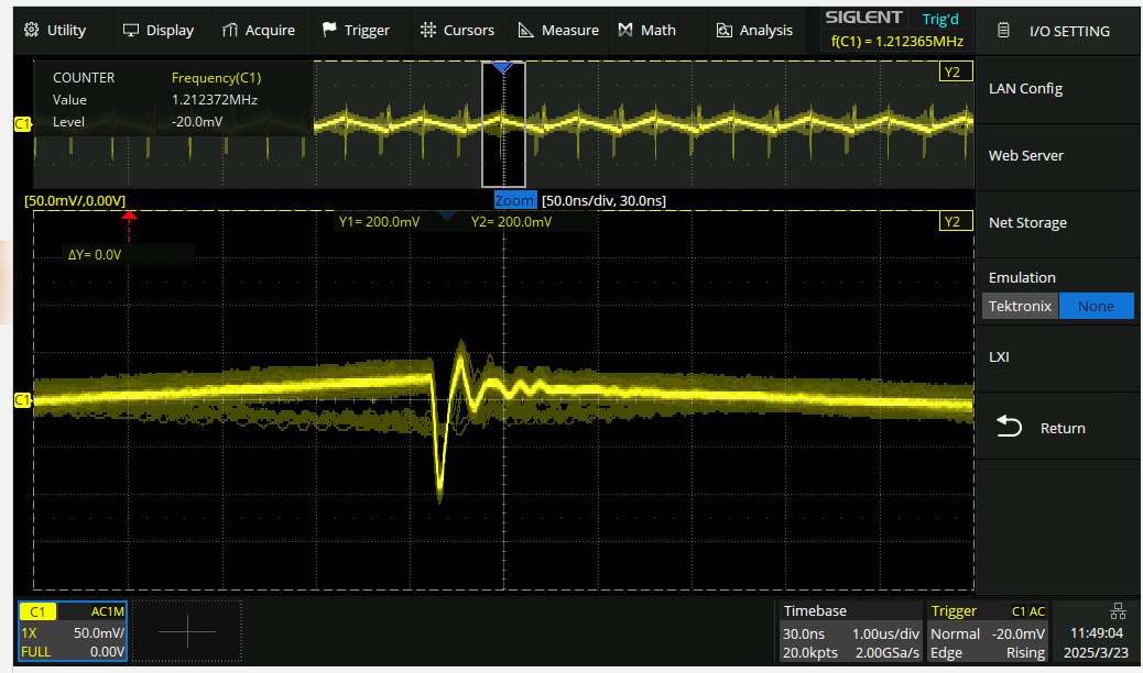
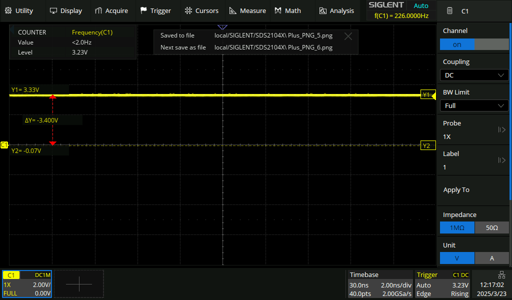
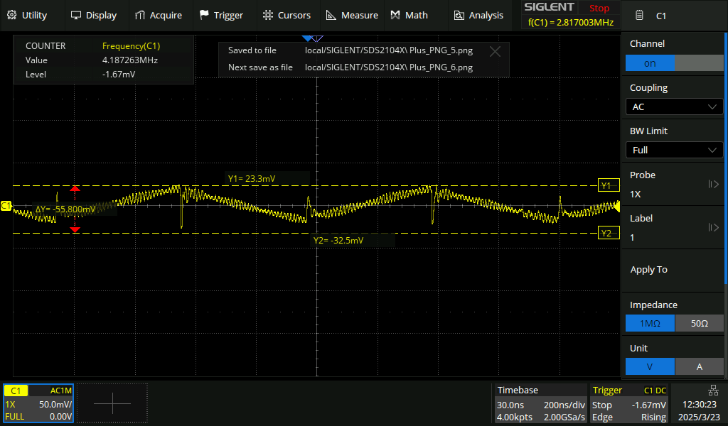
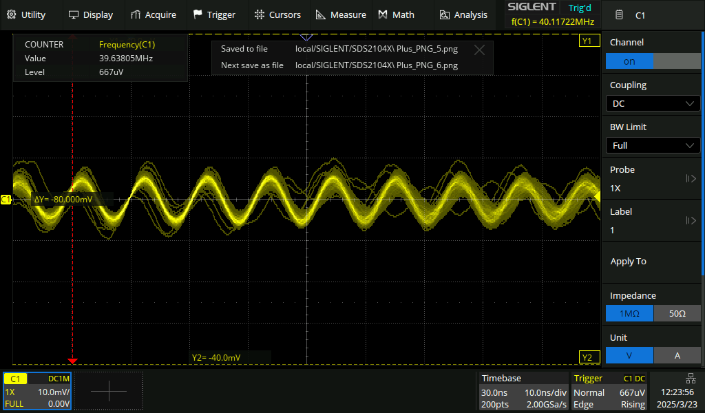
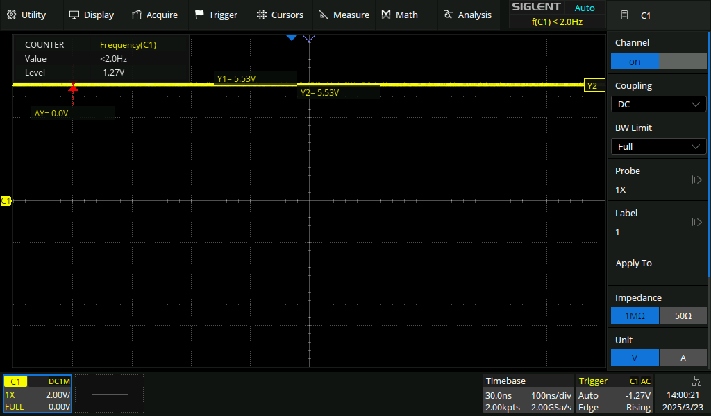
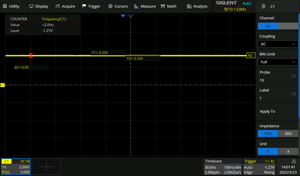
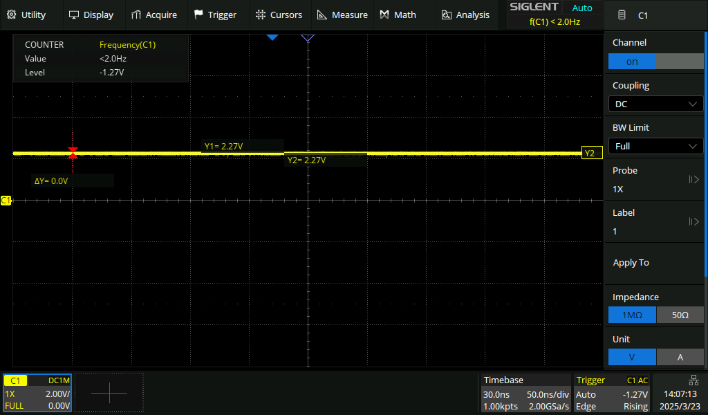
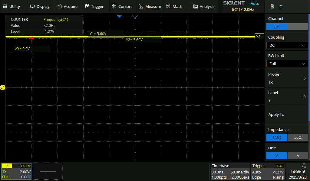
attached measurement in analog mode, No diode, R735=0 and with C715. load is 3 LEDS in series.
Note these are AC coupled measurements except for the input. The DC votlage level is around 5.5 (DIMS=1) to 6.5V (DIMS around 20)
Two measurement voltage over the inductor gave some different results. Don’t know which makes sense.(?)
Device register 0 content is C0h ==> high DIMS of 24 the circuit because unstable and may shut down
LED driver is enabled
DIMS is 10h
Device register 1 is 28h
mode: Analog (LED current set by I2C)
sync: Synchronous
ovp: Protection point is 24V
vos: VOUT is normal
ledo: LED is normal
otp: Temperature is normal
Device register 0 content is C0h
LED driver is enabled
DIMS is 10h
Device register 1 is 00h
mode: Analog (LED current set by I2C)
sync: Non-synchronous
ovp: Protection point is 13.5V
vos: VOUT is normal
ledo: LED is normal
otp: Temperature is normal
I am giving up on this board . It was working great until playing around with the registers and sync mode. It seems there isn’t any guidance how to measure or check if the MP3309C is defect or not., it may be damaged. Will spin the board for a new rev with diode and larger inductor and alternate hardware configuration. Hopefully MPS can add a big red color warning in the manual for:
it may damage the IC internally when you operate in non-synchronous/asynchronous mode without the diode at first when SYNC bit=0.