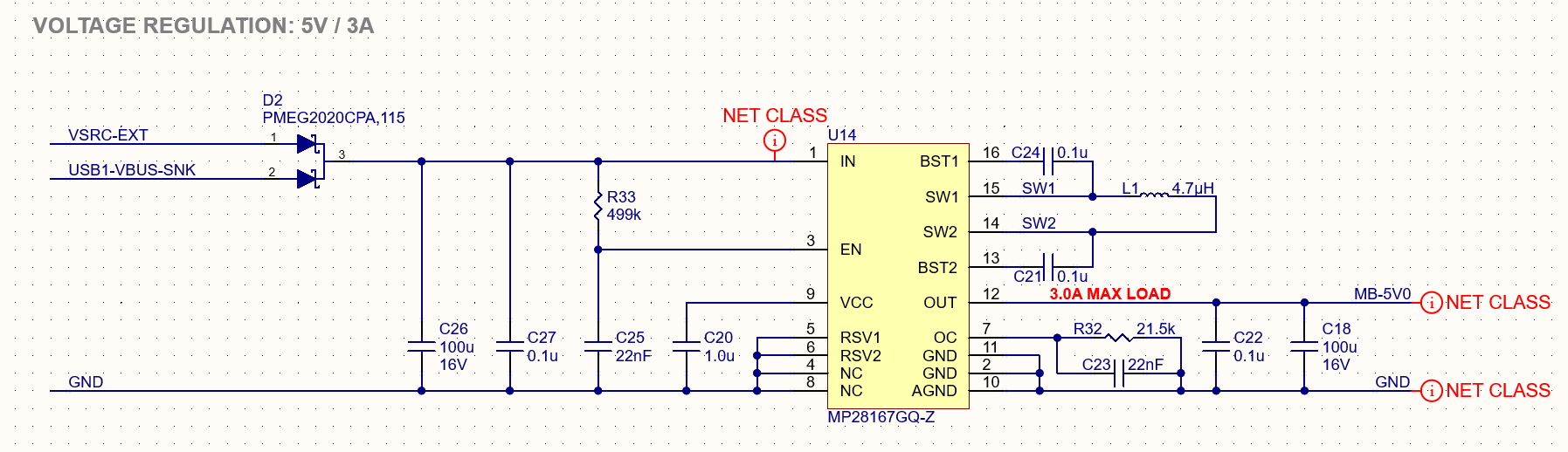
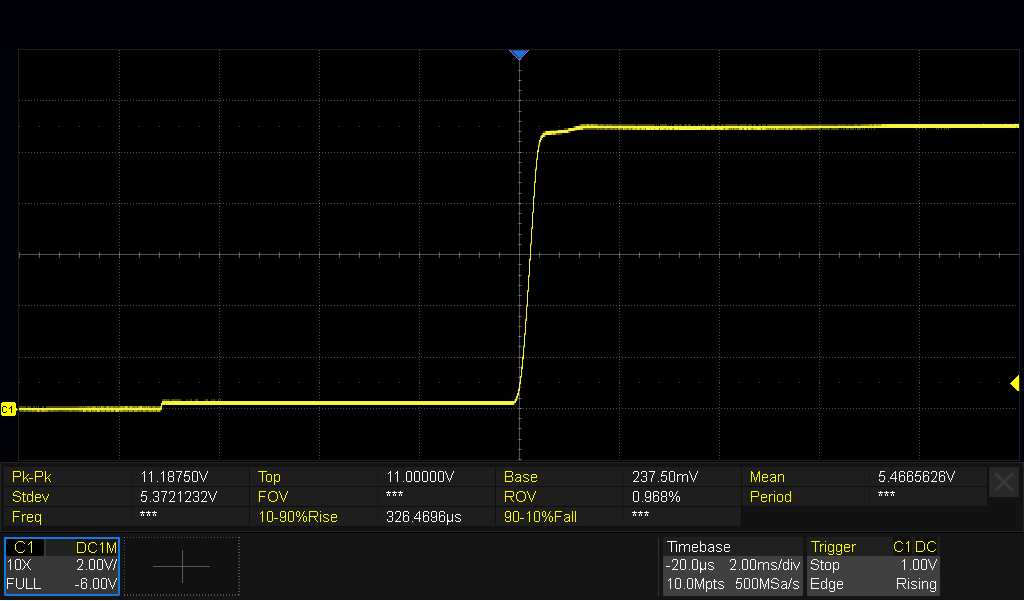
I have a design that implements the MP28167GQ part, which is ‘supposed’ to accept 2.8-22VDC input and ouptut a fixed 5V. The input of this regulator is being supplied via an ORing diode, passing either VSRC-EXT or USB1-VBUS-SNK (which is intended to be an input from a USB-PD compliant circuit adhering to the standard voltage profiles up to 15V). The USB-PD sink interface is slated for future development and not currently populated on the board. I am powering the board from a benchtop power supply set to 12.0VDC output - confirmed via multimeter. In its intended application, VSRC-EXT is never expected to go above ~14 VDC. When I apply power to the input (12.0VDC), I am seeing the output voltage on the MB-5V0 net across C18 track the input, rising up to >11VDC. This is causing a downstream power module I am using to fail, as it only tolerates up to 5.5VDC on input (absolute maximum of 6VDC). It does not even appear to be trying to regulate the output to 5V at any point based on the oscilloscope waveform I included below. I’ve replaced both the IC (U14) and the inductor (L1) but just keep burning out my downstream regulator due to overvoltage. I’ve triple checked and the connections seem to match what is provided in the reference schematics unless there’s some very small detail I’m missing. Any assistance in identifying what could be going on here would be greatly appreciated.
Hello @sbrickey ,
Thank you for posting your question on the MPS Technical Forum.
I can see that you have followed the Typical Application Schematic shown in the datasheet.
The fact that your measured output voltage is very close to the power supply input voltage (~12V) might be an indication that there could be some VIN-VOUT short.
- Have you checked for continuity on the PCB?
- Is this your own PCB, or are you using an EVB?
If you were to provide a different input voltage supply, like 5V for instance.
- What does the output voltage read?
Also, what is the top marking of the IC you are using?
I want to ensure you are not using the MP28167-A , which is the adjustable output voltage version of this IC.
I hope this provides some insights.
Regards,
Edgar
Hi Edgar,
I am using a custom PCBA that implements the power supply as indicated in the attached schematic of my original post. The top markings on the chip are “BJHS 357” which, from the datasheet, appears to be the correct MP28167GQ part.
I’ve performed continuity checks between VIN (probed at C26) and VOUT (probed at C18) with a multimeter, and they do not appear shorted together. I replaced the regulator chip again and ran some additional tests. It appears to work fine up until the input supply reaches ~9.35V (as measured at benchtop supply); it will read 4.98-4.99V out as expected. Once I hit 9.35V, the input current starts to jump pretty significantly and the output starts to track the input; as soon as I bump it back below this threshold, it starts regulating normally again at 4.99V out. I played around with where I was supplying the voltage to the circuit and tried eliminating the ORing diode, but it didn’t seem to matter. Is there any significance to 9.35V input for the 5V fixed output model?