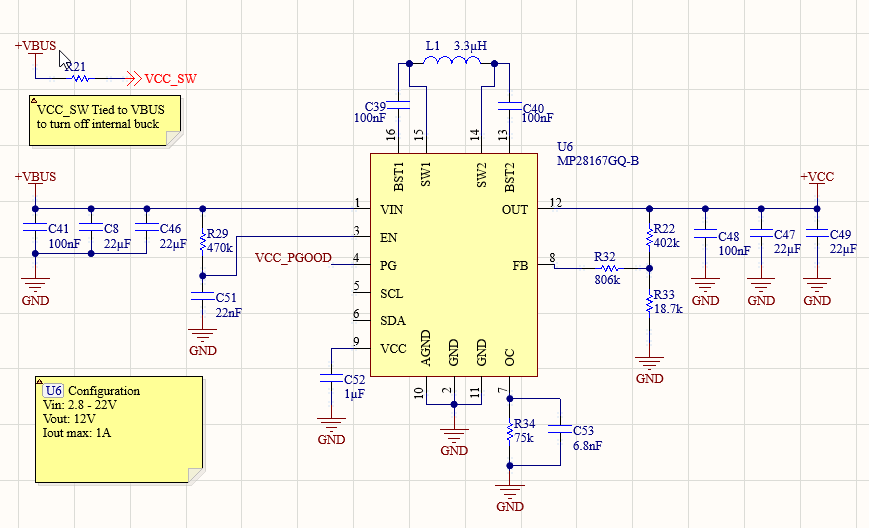
I am using the MP28167GQ-B in my design to output 12V from the V-bus. I followed the application recommendation in the data sheet for the correct resistor set up to achieve this output, but the device is outputting 22V instead. I reread the datasheet and found I missed the unused I2C lines being tied to the VCC pin so I made that fix*(not shown in the schematic pic, but I made it on the board)*, but the device is outputting 18V now. I have checked several times all of the passive components around the device and everything is correct according to the set up in the data sheet. I have tried replacing the device assuming I got a bad chip and it had the same issues.
Any ideas on a fix or as to what is causing this?
Hello Neil, welcome to the MPS Forums.
We have reviewed your schematic as posted and have found no blaring anomalies. The fact that you have replaced the IC with a new one further narrows down the issue.
A few questions:
-
What is your typical Vin when you see Vout conditions at 22V and 18V?
-
Have you verified that the feedback resistances match your schematic?
-
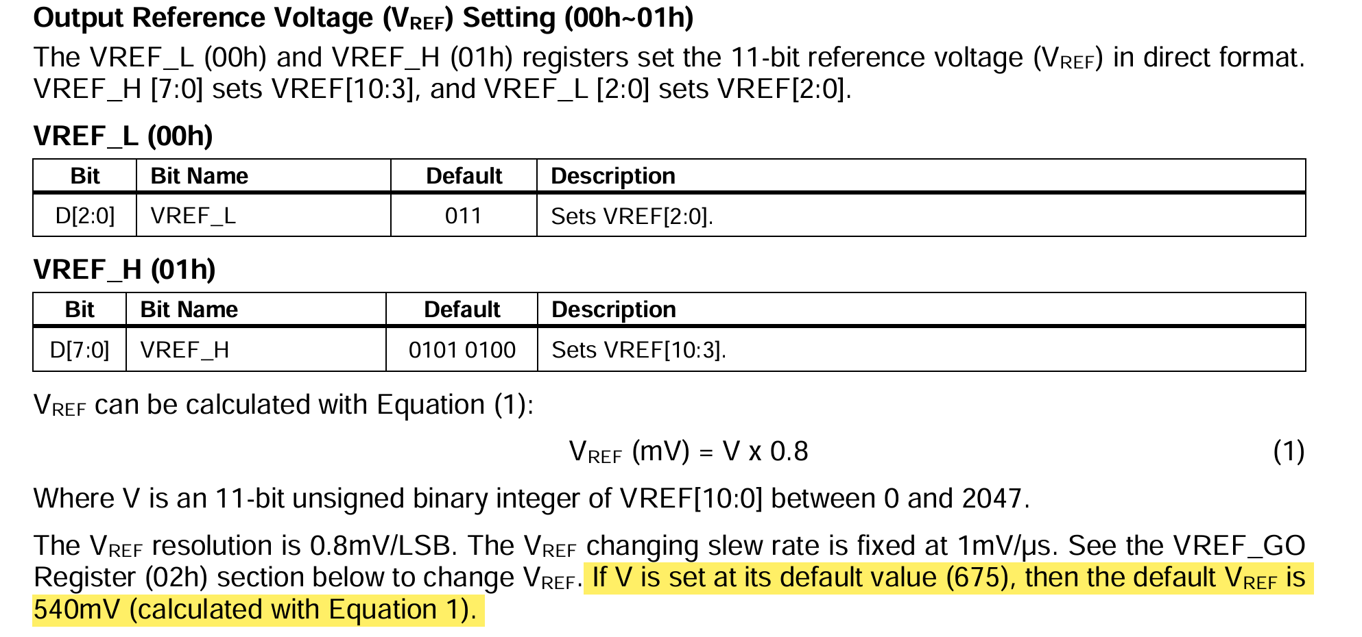
What does your feedback voltage measure to? Is this 540mV?
-
Which variant of this part do you have?
-
Do you have a register dump that we can review? Register 01h for instance changes the value of the default feedback voltage.
-
Is the GO_BIT set to 0? This is done so be default but we just figured this was worth checking as this bit allows Vref to change?
Looking forward to hearing back.
Best,
Krishan
We figured out we had actually ordered the A variant of this part by accident when we needed the B variant specifically. After replacing the A parts with the B parts we don’t have the issue.
But to answer your other questions, just in case its relevant in the future.
- Typical Vin is 12V, though it can be slightly higher as this is for a battery powered device.
- We did double check that all our resistor values were correct according to the schematic.
- The feedback voltage measured at 995mV
- This design does not utilize the I2C lines, so we have left those completely unconnected and thus have no way to change or see the data
Interestingly, upon seeing the feedback voltage as .995V, I checked this in the equation later in the data sheet used to find the resistor values, and replaced one of the resistors to set Vout to 12V based on using that .995, which did end up working. I did not make a note of exactly what the resistor value was, but the equation is in the data sheet so it should be easy to figure that out.
Again, this probably doesn’t matter all that much since we figured out the issue was the wrong part, and not a faulty part.
Right, the A variant of this part is designed for a fixed 5V output and has no I2C capability. It also doesn’t have any feedback pins so I’m unsure to how the output voltage changed…
In any case, I’m glad that you are using the B variant and are seeing no issues.