Hello,
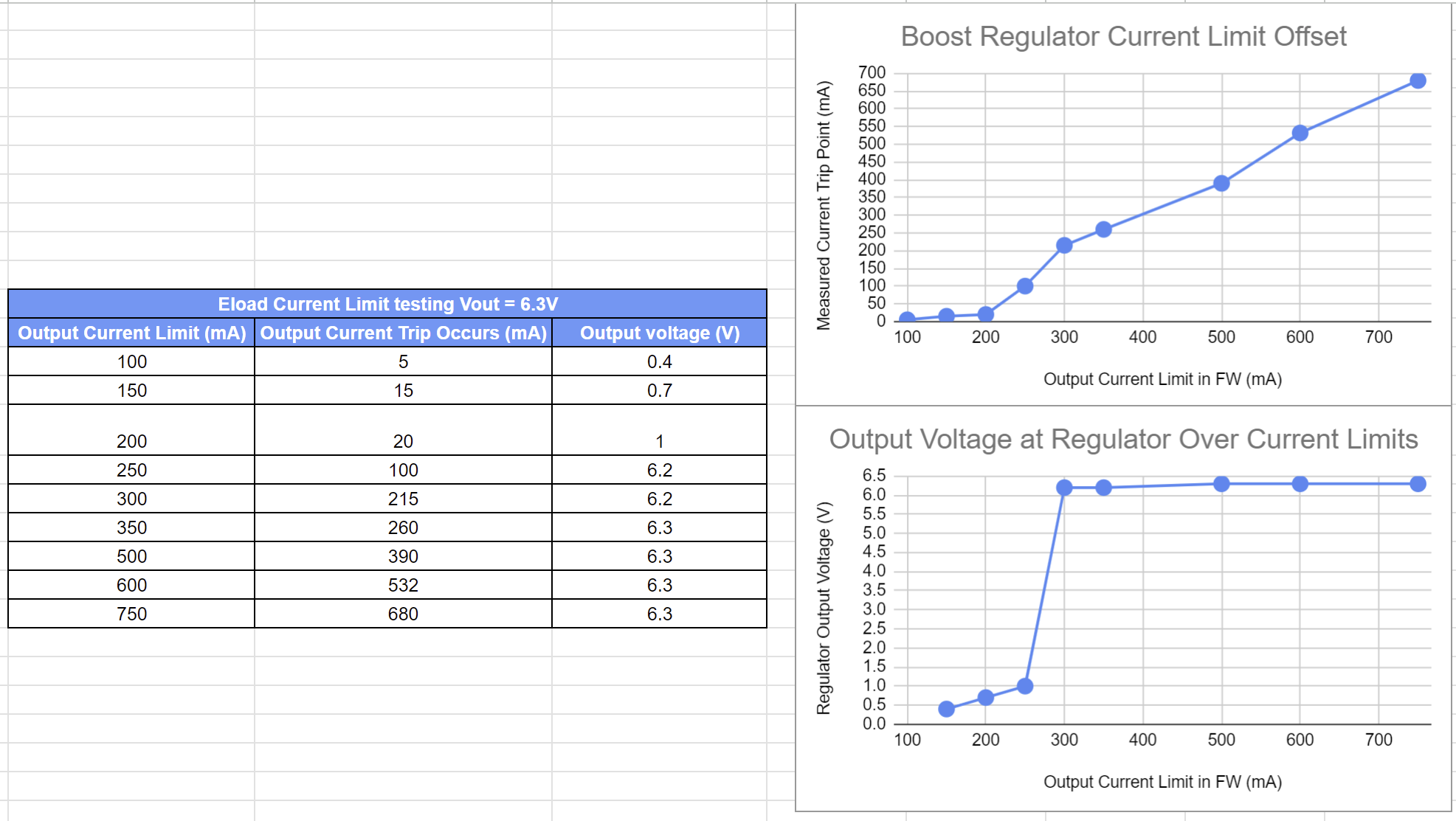
I am using the I2C configurable overcurrent trip point of the MP28167-A for use in limiting my wireless charging applications from hazards. Based on our design, we would like to limit the current to 200mA, but we noticed an offset between the limit set via I2C and the measured trip point recorded by slowly incrementing a constant current electronic load. For example, we are using a FW limit of 300mA and measuring a trip point of 215mA. At low current limit values < 250mA, the voltage of the system is also clamped from its set value as shown in the figure below. It seems that the overcurrent feedback loop is inhibiting Vout at low current limits and drops off in performance quickly below 250mA due to FET quiescent draw or headroom issues. Does MPS have any ideas on why this offset and voltage clamping occur at low current limit settings as shown in the figure below.
A current limit setting with increments lower than 50mA/LSB would be ideal, but the datasheet does not provide any equations on adjusting the mA/LSB. We are using the 22nF and 21.5k resistor on the OC pin. Is it possible to tweak the resistor to adjust the biasing and resolution of the sensing circuitry or is this circuit primarily used to compensate the feedback circuit? Let me know if details of the attachment are unclear or if any other questions arise.