Hi. We’ve included the component MP2760 in the electronics of our in-pipe inspection robot. We need to charge 3 LiPo Batteries of 850mAh (with no NTC), to provide around 12V to SYS.
I’ve configured the component via I2C through a python script.
I’m able to read all the register and everything is ok except for the battery is not charging.
If I read the register of the status 0 (Reg 16h), I can see in the bits 8-7-6 that the phase is Constant Current Charging, but when I read the Charge Current (Reg14h) it is 0 (I’ve configured 800mA of charge current).
In the other register of the status (Reg 17h) everything is correct, and also I disabled temperature protection (due to the batteries doesnt have NTC) and source mode.
We power the MP2760 with 12VDC and we don’t use any USB. I want to isolate if the problem is in my configuration or in the electronics.
Thank you in advance.
Please, can someone help? We’re in a hurry with this issue
I’ve noticed that the Company that made the electronics for us, has not included the ceramic capacitors C3 and C10 that the datasheet recommends between the pin BATT and GND. Could it be the reason of the battery not charging?
Also, I have the battery connected throug wires of aprox 30cm long.
I can provide the python code and the electronic schematic.
Please help.
Hi a.alvarez,
Apologies for the delayed response.
Regards to your latest response, no I don’t think the capacitor on BATT is the reason for no charge current. Those caps are placed to reduce IR drop.
It seems your charge current register 14h might not be configured correctly. Can you read what you have set the register to?
Also, can you show how you are connected BATT and VSYS?
Thanks,
Cindy
Hi Cindy.
Thanks for the response.
As I said, the battery is connected with 30cm wire (aprox), could it be the IR drop that you are mentioning (with the fact that we don’t have those capacitors?)
This is the part of the schematic of the MP2760:
When I read the value that I’ve set in the register 14h, it’s 800 mA.
The way that I’m setting that value is, in python:
config=0x400 #Hexadecimal value of the binary of 800mA
bytes = [config & 0xFF, (config >> 8) & 0xFF]
self.bus.write_i2c_block_data(0x08, 0x14, bytes)
I can send the full library that I’ve made to configure the component.
Thank you in advance,
Adrian
I think I detected something. In the MOSFET, the datasheet of the SISA14DN shows three S pins (1, 2 and 3) and one G pin (4). The schematic of our electronics shows this mosfet:
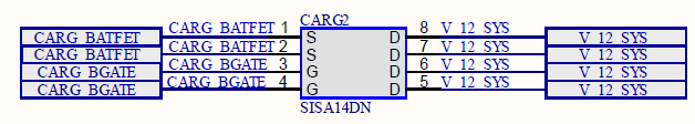
Maybe our electronics providers made a mistake in this component, because it seems to have two S pins and two G pins when the official datasheet does not show that scheme.
