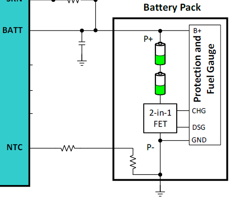
We’re using MP2759A to charge our battery packs. Currently we are using an external thermistor glued into the battery adapter to measure the “battery temperature”. The battery has an internal thermistor, but it is connected to VBATT+ (20V). The data sheet for MP2759A shows NTC thermistor connected between “NTC” and GND, this is the opposite configuration compared with the battery pack. Is there an application note or recommend adapter circuit so we can connect the internal pack thermistor to the MP2759A?
Hi Jimmy,
Thanks for reaching out. I understand you’re looking into trying to connect an internal thermistor to the NTC pin of the MP2759A. To get a better understanding I have a few questions:
- What battery packs are you using? Is there a PN you could share?
- Are there any wires coming from the battery pack? 2 wires or 3 wires?
- Is the internal NTC connected to the negative (-) or positive (+)?

Typically, the Battery pack NTC is connected on the negative terminal of the battery which can be connected as shown in the image above. If the NTC on your pack is connected to the (+) terminal, it will not work for the MP2759A.
Hope this helps!
Best.
Stephen
Hi Stephen,
I’m trying to connect to the thermistor inside a Dewalt compatible tool battery (there are 10k rebrands out there, take your pick). The thermistor pin is connected between TH and V+ (20V) on the battery pack. If it was connected to V-, I wouldn’t have posted. I’m looking for some kind of circuit adapter solution so I can get the MP2759A to read this internal thermistor, rather than use a less accurate external thermistor. I know its not what the MPS2759A is designed for, but its common enough I hoped you would have an app note solution.
Hi Jimmy,
Thanks for providing additional details. I am still investigating your request, and I have reached out internally to our Applications Engineer. I will follow up once I have more information from them.
Probably more trouble than it is worth. Are you darn sure it is connected as you say?
Somehow or other you are going to have to mirror VCC of the chip up to the Thermistor and then shoot the resulting current down to maybe a resistor on the NTC pin. Basically a concept of a plan maybe can do it with a dual op amp and some transistors. It isn’t obvious.
One problem you have is the NTC trip points are referenced as a percentage of Vcc which is kind of poorly specified.
On the other hand NTC’s change about 4% per degree so a 4% error in you circuit is only a degree in temperature probably no big deal.
Yes I’m 100% sure of the thermistor circuit. Don’t ask me why Dewalt did that, boggles my mind. Other option, which isn’t less trouble is to disassemble the batteries, change the thermistor circuit and re-assemble. Or go through all the trouble of finding new vendors and re-qualifying batteries. There is no easy solution. The circuit board solution only requires a 1 time effort.
Brute forcing it you have to replicate Vcc referenced off the postive battery and then build the same network of temperature sensing then level shift the voltage on the NTC back down to the IC.
If you feel lucky just hope that Vcc is actually 5V and then use a regulator to create Vbat - 5V put your sensing network there and use an instrumentation amp to level shift back down to the chip
pretty ugly