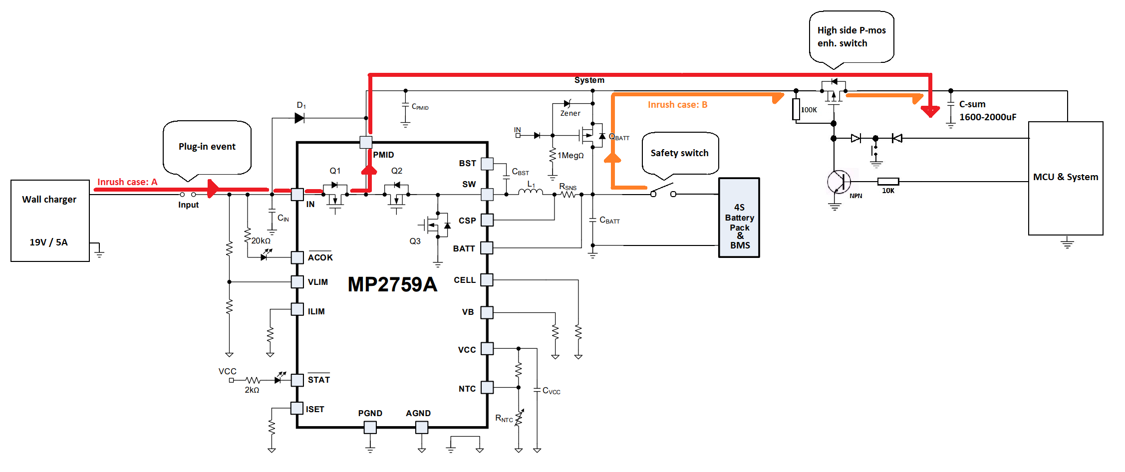
Dear forum members and experts, a few weeks ago I started to design a battery charger with MP2759/MP2759A. My main concern is that the system which will be connected to the IC has a lot of capacitive load. This results in a significant inrush current. The battery pack is a 4S3P Li-Ion 18650 type with a standard cell balancer. The charger is a 19V, 5A capable standard notebook adapter(so far, but it can be subjected to change). The measured inrush current is around 40A-50A for the system. The circuit consists of several capacitances distributed at every major subsystem, it adds up roughly to 1600uF to 2000uF. Which is not a huge value but given the parallel connection, the resulting low ESR causes a relatively large inrush current. I also implemented a P-MOSFET to use the power path management feature of the MP2759. The MOSFET is a “SiR1309DP” type power P-mos. However on the datasheet the “Q-batt” seems to be indicated as a depletion type MOSFET. Is this an error or is it intended to have a depletion P-MOSFET symbol?
The system also has a “safety switch” where the battery with BMS will be disconnected from the charger and from the system. See attached image.
My question is that an inrush current event of above mentioned magnitude in “case A” and “case B” can damage the charger chip when a discharged capacitance of 1600-2000uF is suddenly attached (via another P-mos switch indicated on the diagram) to the power output of the MP2759? Also in “case A” where will be the more current? Via diode D1 or via Q1 trough Pmid?
Any other suggestions regarding the design would be highly appreciated!
Thank you for your answer!
Hi @habel.ervin,
The input current limit can be set using a resistor on ILIM pin. You can choose a resistor which can handle the inrush current as per your implementation. Please refer to the “Input Voltage and Input Current Limits” section in the datasheet.
Since your input is less than 20V, a TVS diode is not req at the IN pin. However, 1uF/50V ceramic cap for adapter applications and a ≥47μF capacitance for solar applications is recommended. For Batt Cap, use a 10uF/50V ceramic cap to accommodate the overshoot when the battery is connected.
Kindly refer to the Input Cap and Batt cap section so that you also account for the voltage spikes if any.
It’s a P MOSFET. We use AM4417P. You can find more information about implementation in the evaluation board DS - EV2579-Q-00A.
Please let us know if you have any other questions.
Thanks
Saurabh
Thank you for your reply!
As you suggested I chose the current limiting resistor for the I lim section. I’ll start the testing of the circuit. Is there a preferred way to evaluate the functionalities without using external batteries?
Also I will use this charger in a 4S10P configuration, which means a lot of charging time. The internal timer will do its job and probably shut down the charging before all the pack is charged. I’m aware of the safety timer reset method, where you pull down the “VLIM” pin, thus resetting the charging timer. Is there a way to extend the timer duration for the preferred charging time (calculated by capacity and charging current), thus eliminating the need of an omnipresent MCU?
Thank you in advance!
Ervin
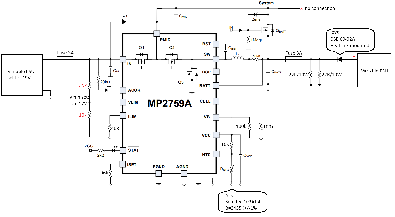
I attached a schematic diagram for the evaluation of the circuit. Some of the resistor values are also included. Please confirm whether this setup is adequate to verify the functionality of the said circuit. (I’m certain that it will suffice, since these measurements depend on the instruments measuring the values).
-battery cutoff voltage
-battery cell voltage setting ( derived from cutoff voltage)
-battery charging current inspection (both max current and current decrease over end of charge)
-thermal cutoff (NTC coupled with external thermometer and heated with a heat source to certain degree)
-shutdown timer and timer reset functionality (with cooled resistors)
-battery overvoltage
-battery undervoltage
Thank you in advance!
For anyone who’s interested, it is possible to evaluate such parameters with the above circuit. You just have to make sure that the resistors have the appropriate power rating. It also helps a lot if you have a programmable power supply and automatised measurement setup. Pay attention to the charge termination point if you try to characterise the charge/termination transition, since it happens in between 16.7V and 16.8V Therefore you need to step the voltage of the PSU with higher precision than between 12V and 16.7V A Two or four quadrant programmable precision high power PSU is best suited for this test.
Hi Ervin, may I know how you resolve inrush current problem and why the 22R/10W is used at variable PSU side?
Any advice would be appreciated. Thank you.