Hello, I use MP2759 With 4S 2P Battery Charging.
I want to Charging 4S 2P Battery.
I made a PCB referring to the MP2759 EVM circuit diagram and tried to charge the battery.
But there was no way to check if the battery was charging.
How do I check if the battery is charging?
The ACOK and STAT pins were always in the LOW state.
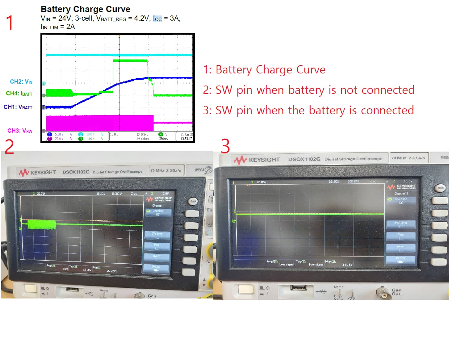
When I checked the data sheet, it was confirmed that the voltage of the SW pin changed during charging, but when charging the battery, the voltage of the SW pin was the same as the battery voltage value.
Any advice on how to check the battery charge and how to fix this would be appreciated.
Hi,
The ACOK and STAT pins can indicate charging state shown in Table3. From ACOK and STAT pin being low, it is in charging state.
Charge will not terminate unless these conditions below are met. If this doesn’t happen, I believe the STAT and ACOK pin status will not change.
Best Regards,
Yu
Hello, I checked your answer.
But, The battery does not appear to be charging.
Input power was applied to 20V, 1.6V for VLIM, 2A for ILIM, and 1.5A for ICC.
ACOK and STAT are always in LOW status as indicated in the datasheet you uploaded, but this is the same even when the battery is not connected.
And when I checked the following datasheet, the following waveform output should be on the SW pin while charging, but the actual result was different.
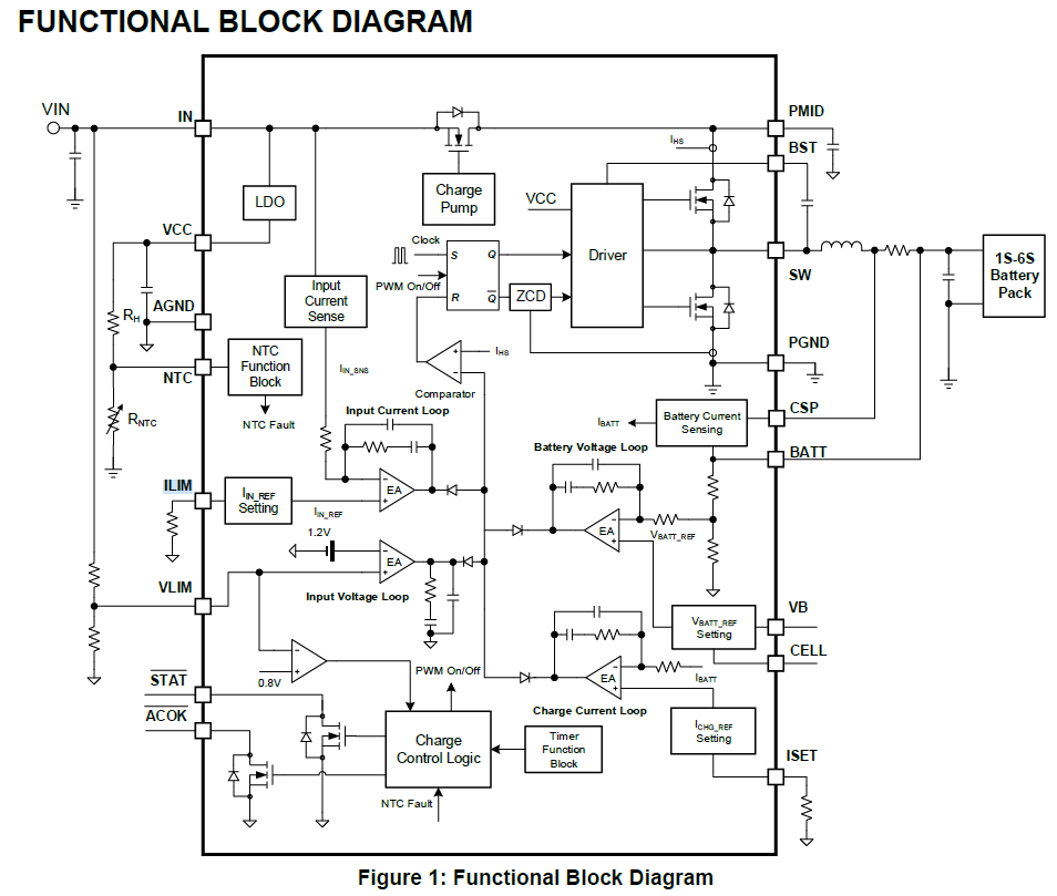
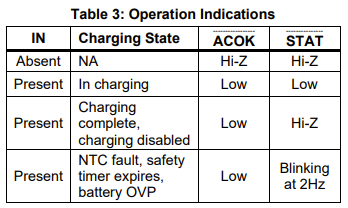
I checked the SW pin status with the oscilloscope when the battery was not connected and when the battery was connected.
When I checked the SW pin with the battery connected, only the voltage on the battery was coming out.
I wonder if charging is going on even though this way.
I would like to ask if you can give me any advice on this matter. Thank you.
You should be able to know if charging is occurring based on the input power. If you had a 7V battery with a 2A charge current then the input power under charging would be 14W plus a little extra. If the AC is not OK it won’t charge so that is your first problem. Once the chip thinks that the AC is OK then it might charge
It charges a total of 16.8V battery with a charging current of 1.5A, 4S2P (4.2V per cell).
Can I know how to charge specifically through the input power source?
Also, we don’t know exactly how to check the AC behavior of the chip.
Any advice would be appreciated.
What is going on at the NTC pin? The datasheet suggests that ACOK should be low if you have Vin that is 2.4V higher than Vbattery in your case that would be 19.2V for a fully charged battery
Have you measured Vin at the chip to verify you have enough?
The NTC pin is approximately DC 2.62V applied.
For the VIN voltage, 20V is applied, so it is higher than 19.2V.
Can you apply a bit more DCV maybe 24V see if ACOK goes valid. Also I would try to get hold of a demo board.
Due to circuit conditions, there is a problem when applying 20 volts or more.
The datasheet says to design a 47uF/50V electrolytic capacitor if a power supply of more than 20V is applied, but I didn’t design it that way.
Therefore, it is a problem to apply 24V power.
I don’t think it’s possible because the demo board is currently unavailable.
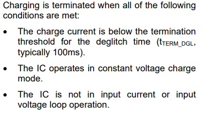
Can you guess why the SW pin pulse is not coming out of this block diagram?
Any number of cases is fine. I will try to solve the problem through this part.
Share each pin or resistance value of the circuit you designed yourself as much as possible.
VIN: DC 20V
NTC: Near DC 2.6V
RILIM: 40.3KOhm (IIN_LIM = 1.985A)
VLIM: Near DC 2V
RISET: 64KOhm (Icc = 1.5A)
RVB, RCELL : 105KOhm
STAT, ACOK: Always LOW