Hi, I’m trying to design a backup battery solution that will fit into an existing space within our product. I believe that 3 x protected 21700 cells in series will give me 11.1V nominal at approximately half the capacity I need and there is room for two such packs in the available space.
I would like to use the MP2759 for charging and power path management - can I charge both 3S packs in parallel from one MP2759, or should I use one charge controller for each battery pack and combine the outputs downstream? Charging time is not critical and the current available for battery charging is limited by the input power supply, so the current drawn by two packs in parallel would not over-stress a single MP2759
You could charge the two parallel packs with one MP2759. You recognize that there will be a slower charging time and that are current limitations.
However, I am worried about cell/pack balancing. With the parallel connection, there is no guarantee that the packs will be charged equally. It may be fine if you are using the same battery.
I would recommend using the 2 MP2759 and combining the outputs downstream.
About downstream combination, how would you solve it? Schottky diodes are enough or is there a smarter solution for this problem? (I don’t think that two MP2759 “System” outputs could be connected directly without confusing them.
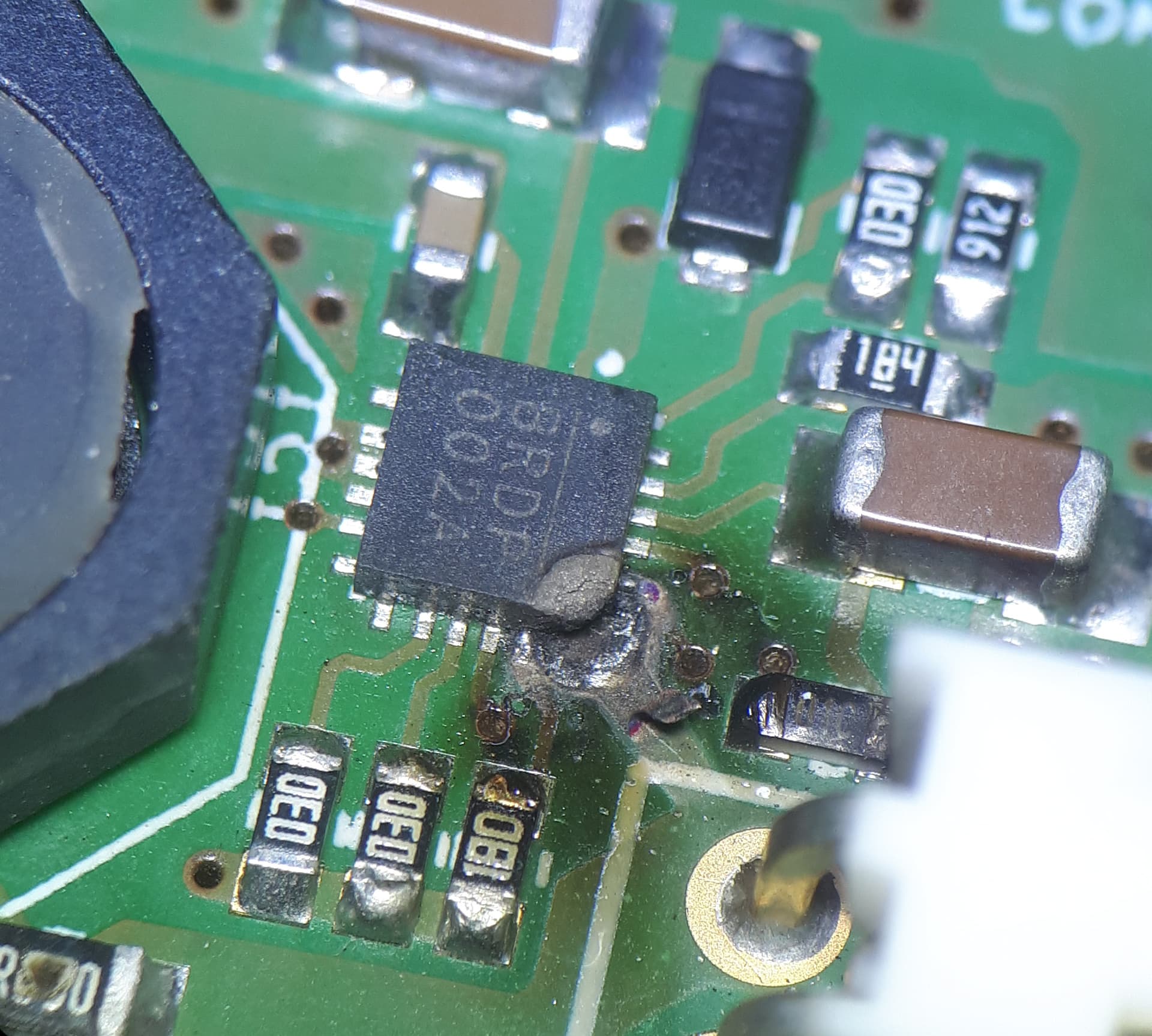
We used four 5Ah 21700 protected cells in a 4S cell configuration, charged by a MP2759. We made changes to the application circuit to handle the higher voltage. Maximum charge current was limited to 410mA and battery discharge current averaged 1A, with short peaks at just under 2A. The first prototype worked fine for 3 months, but has just failed. The corner of the MP2759 package with the battery connection pads overheated, melted the PCB trace and burned the FR4 underneath. We are still trying to work out why this happened
Hmm, sorry to hear that your system failed.
Is there any news about why it happened?
1-2A discharge current is not a lot especially when you use the recommended external P-mos power path management method.
You said that there were 2A current spikes, maybe there were larger ones too but way less frequent. Mosfets can develop failure by cumulative stress. Pcb trace melting and FR4 charring → mosfet short to ground. It would be also interesting to hear the MPS engineers opinion.
This design has been extensively tested and there have been no further failures. We are now wondering whether the MP2759 on the failed board was overheated during hand assembly of that prototype board. The attached photograph shows the damage to the charger chip