Hi,
Since the MP2731 already has a buck converter, it would be neat if this could be reused by the application while the battery is not charging (of course).
I have not dived deep into this. But placing a MOSFET switch (MCU controlled) between the battery positive terminal and either PMID or IN on the MP2731 could perhaps work. Then Q4 (batt switch) in MP2731 could be turned off by register. Then NP2731 is “tricked” into having the battery supplying the MP2731.
Using a diode in front of the actual wall-power adapter input, monitored by an MCU, could determine when an actual external power input is present, so that normal charging could be set.
Would this idea work? Or is it best just to add an extra buck converter to the application?
Thanks.
Hi hcglitte,
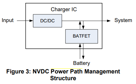
I am not sure if I understand your application properly. It sounds like you just want to implement power pathing. Where the system can be powered by the battery.
A concern I have with your application is the switch control through the MCU. If not programmed properly, it could lead to headaches during the testing. I am not sure if the device would be tricked properly. I am also worried about how now your output node would be on the SW pin. This may lead to damage to the device. The idea just sounds to add complexity to your design. Using a dedicated buck converter chip is the simpler solution in my mind, but I am biased.
Regards,
Vinh Tran
It would definitely add complexity. And, when thinking about it, the input voltage to the MP would be 4.2V down to 3V (lipo range), and I suppose this is lower than the operating range for the MP (not checking datasheet now).
If such a device would exist, it would save another buck converter.