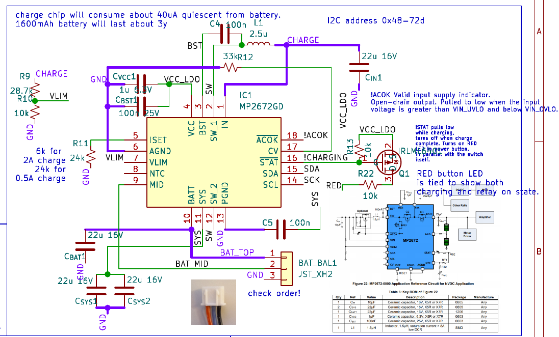
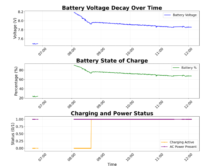
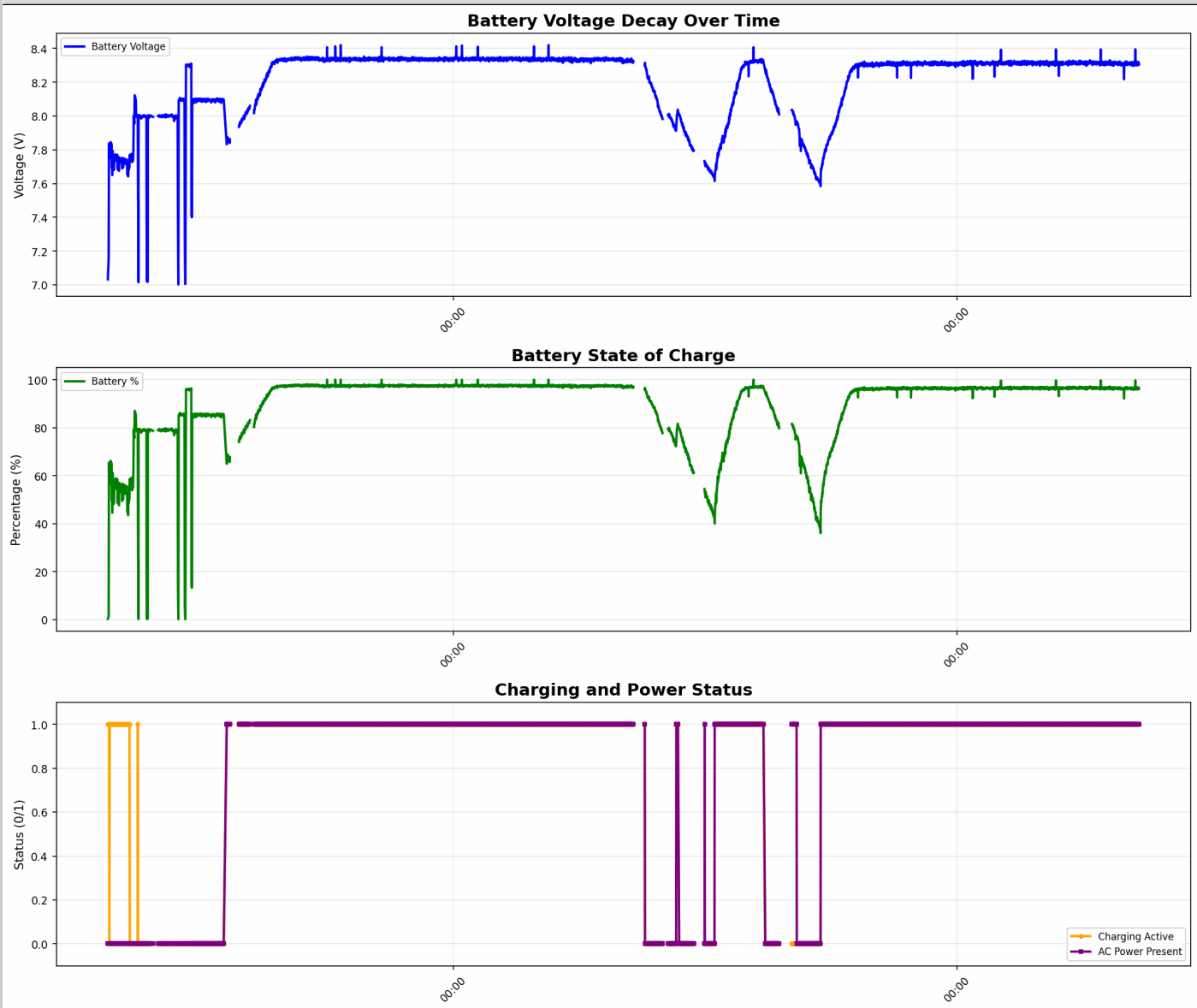
My PCB has this circuit for MPC2672. I initally soldered a 24k resistor for R11 (RIset connected to MP2672 pin 5 ISET) and observed USB 5V VBUS current of 500mA during low-battery charge. However this was insufficient power to power my SBC OrangePi system while battery charging. So I changed to R11=24k. No change in VBUS current, still about 500mA. The USB power supply can supply over 3A and I have observed another charger reaching over 3A. I can confirm that charging slows battery voltage decay but it does not provide sufficient current to keep the system running while charging; see the plot below from my system. Initially I did not have USB power plugged in, and later plugged it in. My system clearly consumes more current than the MPC2672 can produce.
Any suggestions welcome.
Note 1: I soldered a resisitive divider for the missing NTC voltage to put it halfway between limits.
Note 2: I neglected to include the 100Ohm MID resistor on this version of PCB. Not sure how this could affect charge current.
Here is MPC2672 circuit. IN (VIN) comes from USB VBUS power called CHARGE.
It could be that my PCB traces from MID and BATT are too thin; they are 0.2mm traces on 1oz (35um) copper and google tells me a 10cm trace is about 1/4 Ohm. I will check this. I fixed this on upcoming rev of the board but will check it by soldering blue wire jumpers directly from pin to JTC connector today. Could this be the reason? I.e. could the MPC2672 be thinking it has already mostly charged the battery? It doesn’t explain why the current is so low even when the battery drops down below 7V…
Also, I soldered an inline 100Ohm MID to battery MID resistor and that made no difference.
It would be nice if monolithic could comment. The chip seems very well-designed but it is complicated for newbies.
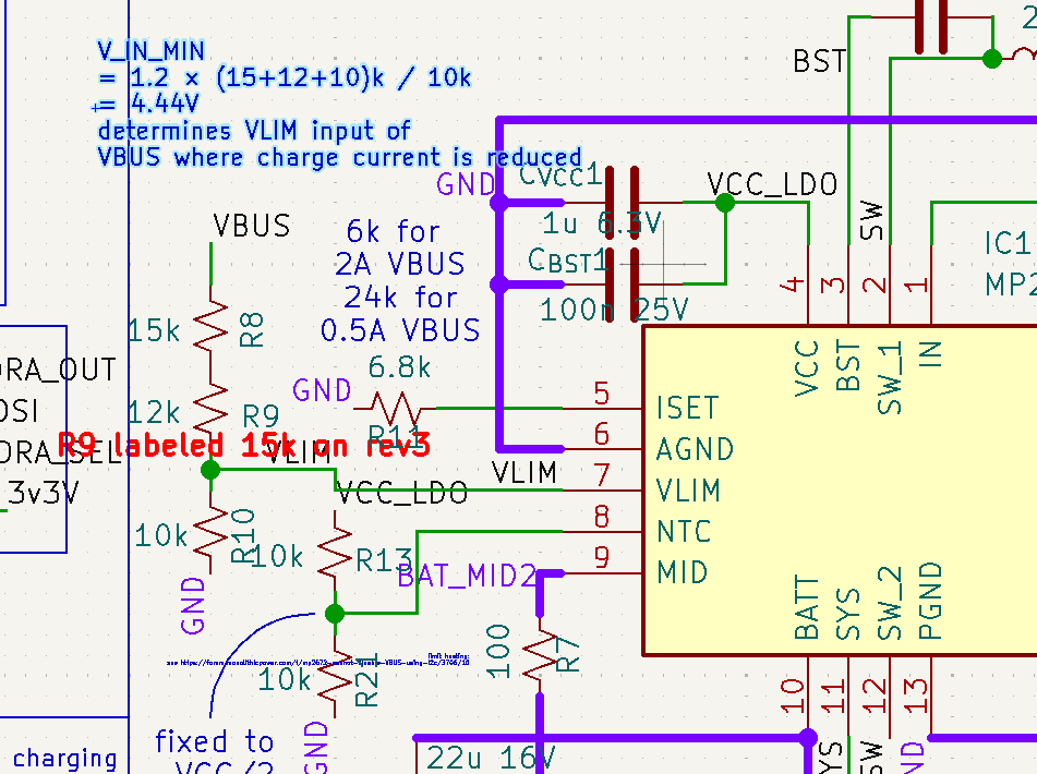
I finally tracked this down to the VLIM input. I was using RH=30k and RL=10k and the threshold of 4.8V for reducing charge current was too high. By reducing RH to 15+27=27k I could reduce VINMIN to 4.44V, which increased the charge current to about 1A. I think I can reduce RH even more since the charge current seems to be a soft function of this voltage.
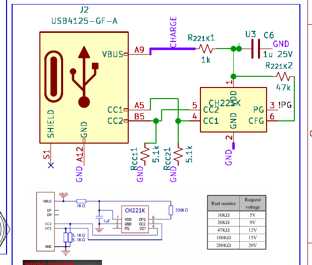
Incidently, I was a bit surprised at the big drop in VBUS getting to my PCB from the USB power supply. I’m using a high quality supply and my USB power meter reports about 4,91V at the supply. But by the time it gets to my PCB USB power header its onlly 4.45V. I used several different USB cables and put the power meter in and out. The USB power meter reports a current of about 1A now. I don’t actually know how that translates to battery charging current (I don’t have any shunt resistor).
One more update: I reduced RH to 8.2k+15k and kept RL=10k and with a resulting VIN_MIN threshold of (8.2+15+10)/10*1.2=3.98V I get >1.5A drawn from USB VBUS now. And I can see that VIN at the MPC2672 is drawn down to 4V during heavy charge. It all makes sense now. Here is latest discharge/charge plot: