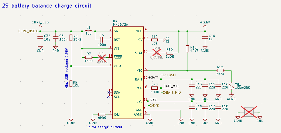
I have designed a system that charges 2x 18650 batteries which supply the system that uses approximately 500mA in normal operation. The system is supplied from SYS pin and the batteries are charged from the +BATT pin (see picture of the schematic).
With my configuration, the batteries are supposed to be charged by ~1.5A. However, according to my USB telemetry tool, it’s saying that when the system is off, the charge current is usually ~2.8A and when I turn on the system, the USB is drawing ~3.6A which forces the adapter to sag its voltage.
What could be the cause? Am I missing something obvious? I find it kind of strange that the same ground that charges the batteries is used by the system, but that’s what the datasheet suggests.
Your ISET pin configuration looks right in the sense that you have your Icc charge current set to 1.5A exactly given Riset = 8kOhms. This would then lead me to ask what bits are set for REG01h. The Icc bits are set to 1111 by default.
Is VCC being pulled up to some external 3.6V source? This is already a 3.6V output that is responsible for powering internal control circuitry.
What are the voltage ratings of each of your capacitors for the Vin, Batt, and Sys rails?
The charger works in “standalone mode” and I’ve relied on setting the charge current purely on Riset. I don’t have SDA/SCL lines connected to any MCU. Is there another way I should’ve set the REG01h register?
No, the +3.6V is meant to signalize the output value of the VCC pin. It is not connected to anything outside of this schematic section.
I’ve checked, and they are rated for 16V and above. Most of them are rated for 16V actually. The inductor is rated for 11A and has a saturation current of 14A.
I have thought about isolating the ground better because turning no my load drastically increases the charge current so there must be some direct correlation between the two that I haven’t figured out yet.
Understood on all feedback that you have provided.
I suppose if you haven’t interfaced with this charger digitally, your registers would likely match the default values.
Noted on the schematic nomenclature for VCC, thanks for the clarification.
Capacitor voltage ratings seem fine, a rule of thumb that we employ in our design would be to make sure the voltage ratings of the caps are 2-3x the voltage rail to account for any derating. Your inductor current and saturation ratings seem appropriate here as well.
Please keep us updated on testing when isolating the grounds better as you mentioned.