Hello everyone,
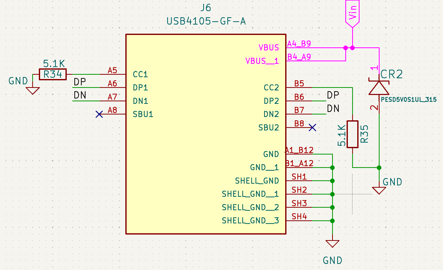
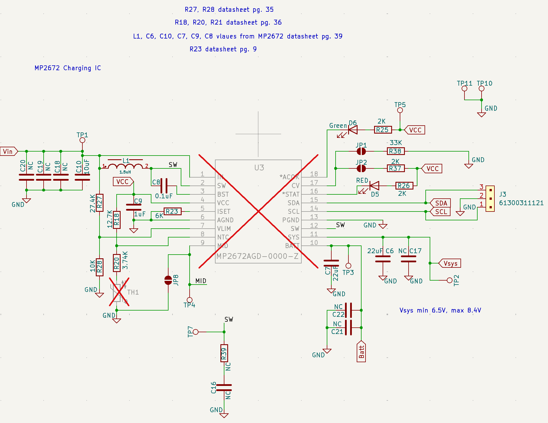
I’m using the MP2672 charging IC in standalone mode with USB Type-C (5V) powering VIN and an ESR protection diode at the input. Initially, everything worked fine, and the batteries charged as expected.
However, after some time, the input ESR diode burned out. I replaced it and continued testing.
Now, whenever I connect only the battery (no VIN power), the MP2672 powers on, which shouldn’t happen — VIN is supposed to be floating. I measured and found that VIN and BATT are internally shorted.
To verify, I soldered a new MP2672, and this time, VIN and BATT are not shorted, confirming the previous IC was damaged. Why did this happen and how to rectify this issue?
Hi,
Can you share the schematic for your design here?
Which diode did you use at the jnput ?
When you connect to the battery, in your case, as the input voltage is below UVLO, thus it turns on the IC via Q3 which is internally connected. Refer to the note on page 18, section “Input power start up” in the datasheet.
Regards,
Adhish
PESD5VOS1UL_315 is the ESD Diode
I know about Input Power Start up, but it occurs when Vin is below 4.3V (Vin UVLO), but I have not connected Vin at all (no input source) but still Vin was measured 4.9V, with only the cells connected, and the IC turned ON.
I have made the design as close to EV2672-D-01A as I could:
Hi itsmeayushzile,
Thank you for sharing the schematic. Since this issue we have never seen before from our end. I will try replicating from my end.
When you say the IC is ON, is it switching and charging the battery as well? For this can you share the waveforms as follows with Vin connected and without Vin connected with battery at the output in both case. Try to have a scope capture at these IN, SW, VBAT, VCC, VSYS signals.
Regards,
Adhish
This topic was automatically closed after 10 days. New replies are no longer allowed.