Hi there,
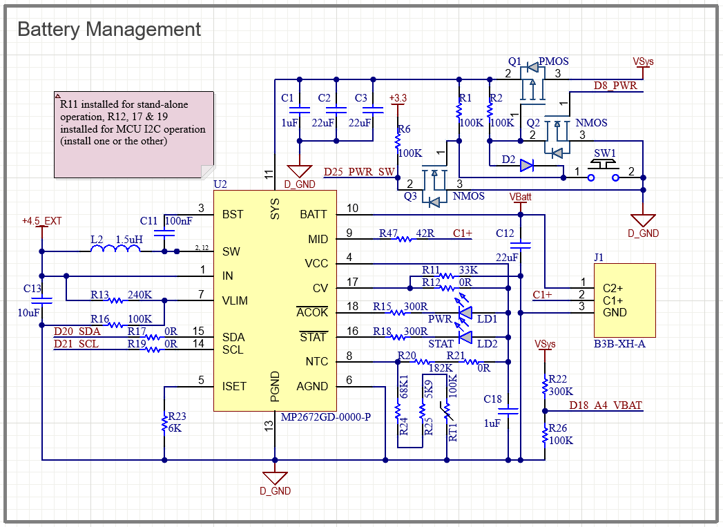
I have a prototype board incorporating the MP2672 to charge and balance a 2S 18650 pack, the board operates normally on battery power alone. External power for charging is applied via USB or 5V DC jack (through diodes to isolate from each other). I have found that when external power is removed I lose communication with the MP2672, which I think is due to the IN (pin 1) being fed from the external supply only. If this is the case, is there a recommended way to power the IC when the external supply is disconnected? Here is the schematic for reference:
Hello peakeelectronicinnov,
What is your system voltage at? Would it be possible to power the i2c lines from Vsys? You may need a voltage divider to fit within the pins absolute values.
Regards,
Vinh Tran
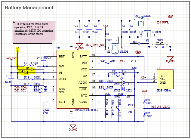
Thanks for your reply Vinh, I do have a 5V buck supply fed from VSys (and 3.3V LDO off that). I’d need to keep this isolated from the incoming power path so would something like this work do you think?:
Hello peakeelectronicinnov,
I may have misunderstood your question. Are your i2c lines being pulled up by the external power source used by Vin? Or is the pull up voltage not affected by the external Vin?
Regards,
Vinh Tran
The pull-ups are supplied from a 3.3V LDO which is supplied from VSYS, so this is always powered, but if the external USB supply is not connected I have no communication with the MP2672. I assume that’s because there is no supply to Vin without the external supply connected? The above OR-ing diodes would supply Vin all the time without back feeding the charge path.
Hello peakeelectronicsinnov,
That could work since VCC is powered by VIN. VCC is used to power control circuitry.
However, my concern would be for battery life and how much of it would get drained when idle.
Regards,
Vinh Tran
Ok thanks Vinh,
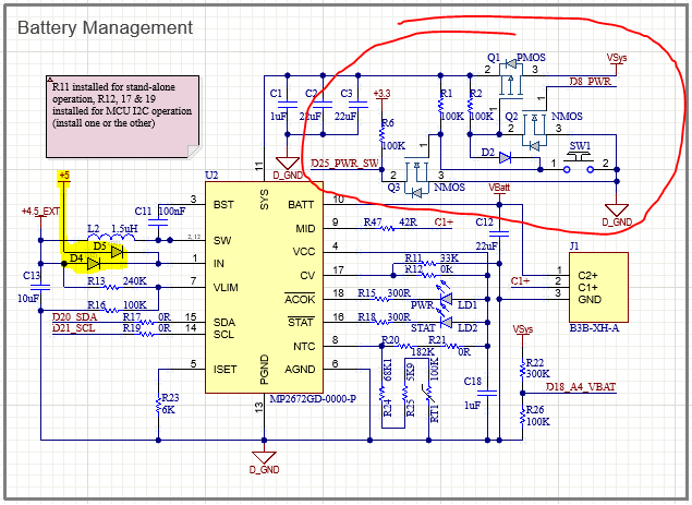
This portion of the circuit controls power to the regulators so when the circuit is off current flow from batteries should be very small. As I’m only interested in communication with the MP2672 while the mcu is running that should be fine, I imagine if Vlim is out of range and there is no current supply into SW the current into IN should be very low even when the circuit is on… One way to find out I suppose 
Hello there, and sorry for bumping the topic which is identical to mine.
As far as I understood from the messages above, The MP2672 core is not working if Vin in not supplied and I am totally ok with this: if the IC gets a NACK, easy peasy, the battery is not charging!
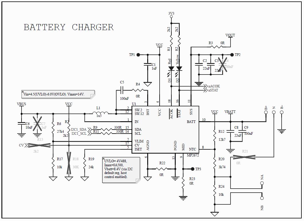
I’m working on a custom handeld system, which makes use of a MP2672 to charge the internal dual cell LiPo battery from an USB 5V when installed in the docking station. The “SYS” pin is used to drive a 3V3 LDO which power a MCU which communicates via I2C with the MP2672, configured in an “host controlled” mode, to ask for battery status.
330R resistors are placed between MP2672 and the bus in order to protect the bus itself, 1k8R pullups are tied to the 3V3 described above (also tried 10k with no differences). nACOK and nSTAT are also tied to 3V3 via two LEDs, for MCU direct readback.
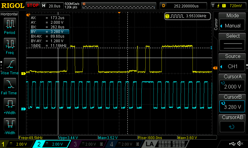
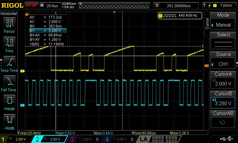
The problem is that when external supply is removed the MP2672 appear to drain current from the DATA line (no problem on CLK line) preventing any use of the I2C bus, e.g. between the MCU and the I2C display installed on the same BUS/board.
We’ve actually take the workaround in setting the MP2672 in “Standalone mode”, mounting R18 below and removing R7, thus losing the possibility to communicate with it asking for battery status.
Am I doing something wrong? Thanks in advance for any answers.
Thanks for posting this interesting observation.
I have the same aim, to charge a robot 2S battery from USB either when the MCU (OrangePi SBC) is off (unpowered) and I plug in the USB charger cable, it powers the MP2672 and charges the battery in standalone mode and I indicate charging via LED from !STAT pin 16. When the MCU is on and I plug in the USB charger cable, I want to be able to monitor battery charging via I2C and supplement the battery power from, USB via the MP2672.
I’m concerned that if I connect the MP2672 to I2C lines, it will prevent normal I2C operation with other devices when it is unpowered. Did you find a solution for this problem?
I suppose I can also connect the host control pin CV to the MCU via a resistor and program the host control mode so that when I plug in USB power, the MP2672 can go to host control mode.
As a fallback, I will put some 0R jumpers to allow options.
I would be grateful for any advice here.
I’m running into the same problem, but I can update something, forget about writing CV (host control mode pin) after power up to change the mode on the fly. This pin is only read on power up, much too early for any firmware to modify the MP2672 mode.
And I’m also running into the same problem: In host control mode (i2c lines connected to my i2c bus and CV tied high), if I power on my controller and the MP2672 is not powered (USB VBUS supplying VIN power not plugged in), then my i2c bus is rendered unusable for any device on it. This seems a bad design choice! The only way I can get host control mode to work is to power my controller with USB power plugged in. Not useful for me.
I gave up on this for now; not worth spending another week trying to figure it out. The register information would be useful and it would be nice to control charging from my controller, but in lieu of some authoritative answers here about the i2c bus status when USB power is absent, I don’t want to spend more time on it.
Going back to this problem again, the basic problem (and it has not been solved) is that if USB power is not plugged in (to SYS), the MP2672 cannot talk on the i2c lines and worse, it prevents any other device from using the same i2c bus! Reading above again suggests that if we power MP2672 VCC from some other source, then MP2672 could talk on i2c bus even if it cannot charge. Is this correct? But this doesn’t make sense because VCC is generated by MP2672 LDO regulator.
In my PCB, the main power from battery is cut off by a relay, so I have no source of power except a direct battery connection to SYS, which would drain the battery continuously.
Could someone from company please comment?
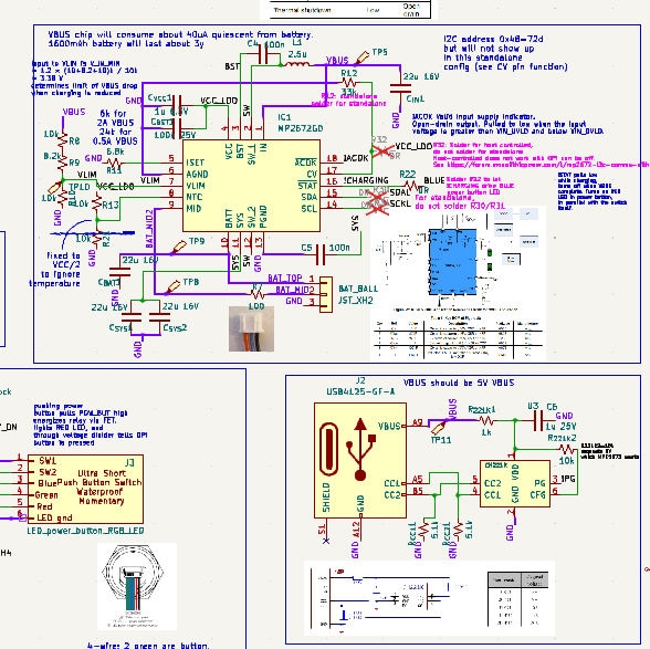
I pasted schematic here. MAIN
I made a new post about this topic at MP2672 I2C with no USB power since this one went stale.