I ‘stumbled’ across the MP2667 looking for a solution where we can charge the battery with solar and switch to the battery when the solar drops without disruption to SYS power. Since this part says it will do this our only issue is current, we need 1,500ma MAX but the data sheet states 1,000ma IIN and 1,600ma ISYS. How does that work?
Hi kangus,
The MP2667 is a linear charger with a max input current limit of 1A and a max charging current of 1A. The system can output 1.6A with the help of the battery discharging to help power the input:
This also means the device can discharge at up to 1.6A from just the battery in the absence of the input.
Does this help clear things up for you?
Thanks,
Brendan Schoemehl
Field Applications Engineer
Monolithic Power Systems | MPS Now
That works for us, now I just have to wait until Mouser gets some, I put 10 on back order for some prototypes I’m layout now.
Thanks for the quick reply
Kevin
Hi Kevin,
Awesome, glad to hear that. Hopefully Mouser gets some devices for your prototype soon. Let me know if you need anything else.
Thanks,
Brendan
While hunting a boost solution I found MP3423GG-P (bye TI)
In a perfect world the MP2667 would merge with the MP3423GG-P and grow some extra registers for battery and IN; for voltage and current, average and peak. The MP3423GG-P is way over kill for our use and considering the MP2667 MAX 1.6 current limit but it will do.
The MP3423 is a great part to pair with battery applications due to its low quiescent current. What specs do you need met on the boost converter? Something like the MP3414A may be another device to look at considering its lower switching current. There are other devices as well that could potentially fit in between the MP3414A and MP3423.
Some battery charging devices offer what’s called “on the go” where they can boost from battery voltage to the system output. This would require a switching charger, which is quite different than the MP2667 which is a linear charger. We usually recommend linear chargers in applications charging a battery below 1A. Anything above 1A we recommend switching chargers, many of which have power path capabilities where they can boost on the output. Let me know your specs and I may come back with a better device for you.
Brendan
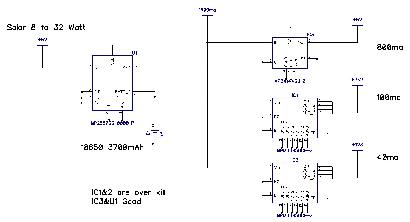
Here’s an overview of what were doing: The main device is a LTE transceiver with PEP that hits double the suggested current (600ma) The 3.3v supply powers another MPU which does the sensor data collection and storage. The 1.8v supports ultrasonic transducers that measure open channel water velocity and wind velocity and direction. Hopefully in the future when Nordic has worked some issues we can drop the second MPU and run everything on +5 and 1.8v.
Two years ago I needed 3amps for the LTE M1 devices, all of them, some more than others but they all sucked power, was looking at 50 watt solar panels. with 10Ah sealed batteries.
Kevin,
I may want to take this offline in order to protect your project and what you are working on. Can you email us at mpsnow@monolithicpower.com to continue our conversation? I will be sure to help you out there as well.
Thanks for sending over your block diagram, this looks pretty solid so far but I do have a few questions.
- What is your charge current for the battery?
- What is the charge voltage on the battery and how low will you run the voltage down to?
- Do you need I2C?
We could potentially move to a switching converter with its own boost capability to 5V depending on your answers. You may want to keep the MP3414A or another boost (depends on your battery voltage answer) for voltage ripple reasons, but testing out devices on an evaluation board would help confirm ripple requirements. I’m narrowing down the possibilities on the best approach here. Go ahead and email us and I’ll be sure to help you out.
Thanks,
Brendan