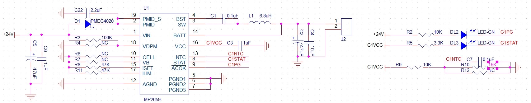
Hello: I built a circuit with MP2659 to build a small 4s battery charger. The schematic diagram is as follows:
Now the problem is: I use a 4s2p battery for testing, when the battery voltage is relatively high (tested 16.1V and 16.3V), when the circuit board is powered on and then connected to the battery, it cannot be charged, and the cable connected battery can be charged when it is powered on again. A 12V battery was tested, and it can be charged by connecting the battery after powering it on. Excuse me, is it normal for the above to happen?If so, what could be the reason? How do I debug? In addition, I found a EV2759A-Q-00A that I bought before, tested it and the phenomenon was the same. Could it be that this is how your chip is designed? Is it problematic that the battery cannot be recharged if it is not fully charged? Thank you
Hello,
Since you are using 4 series cells (4.2 approximately x 4) and you mention that your battery network is 16.1V - 16.3V, then your battery is already about 96% - 97% charged. Charge current tends to slow down or limits all together depending on what your full charge threshold is.
Since the 12V battery was charging, (12V / 4 series cells = 3V per cell) which is below the full-charge threshold makes sense. For your original 4 series cells, have you tried charging when these cells are deeply discharged?
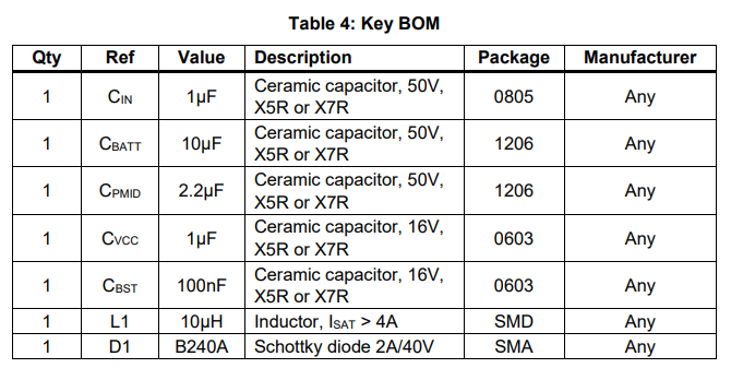
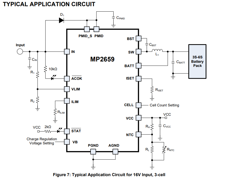
Here is the typical application schematic for your reference. The only differences that I see would be the extra 47uF for Cin and Cbatt, which I don’t think should cause any issues. I would suggest testing with the deeply discharged battery. Let me know if this works.
Best,
Krishan
Hi,
Thanks for your reply。
I just tested that I connected a battery pack that was discharged to protect to the test board and it charged normally.
I also tested two battery charges, and the aforementioned phenomenon occurs when the battery voltage is around 15.8V.My battery pack voltage is 15.75V, the circuit board has been powered, and there is a probability that the battery will not charge when I connect the battery to the battery port of the charger. In this state, keep the battery connected, the circuit board can charge the battery by powering it back on
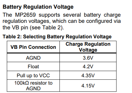
Interesting. Seems as if the battery charge regulation per cell is set lower than you think.
What is the lowest voltage this phenomenon occurs at for your battery voltage?
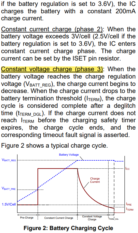
It sounds like you are hitting Phase 3 charging as described below at (15.8V or 15.75V / 4 cells = 3.95VV or 3.94V cell threshold for charging to either limit or stop.
See charging phases below:
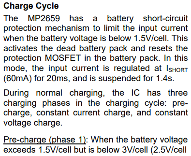
Let me know if there are any updates from this information.
Hi,
I tried my MP2659 board and EV-2759A-Q demo board,it seems the voltage threshold is about 15.8V.I use TI BQ24610 before,and i have never met this phenomenon.
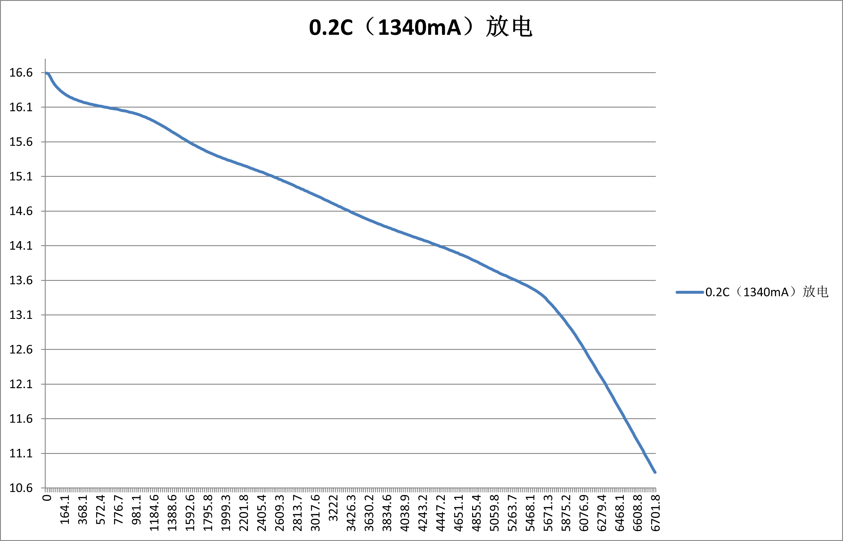
In addition, the following figure shows the discharge curve of our 4S2P battery. The approximate capacity of 15.8V should be about 80%. So it doesn’t exist because the battery voltage reaches the threshold (VBAT_REG) where the charge current decreases. Even if this were the case, the battery would be charged at a low current instead of stopping when it is connected to the charger, and there would be no situation where the battery can be charged or not depends on the sequence in which the battery is connected and the charger circuit board is powered on, right?
I have a video that I recorded at that time, and I can see this phenomenon in the video, and I don’t know how to send it to you? Can you provide an email address?
Thank you
Hello again,
You make a good point here considering the fact that 15.8V is only about 80% to full charge.
It could be that the MP2659 interprets a pre-connected 15.8V as already above the re-charge threshold. Try the following:
- Skip starting a charge cycle
- Only re-initiate charging if the battery drops below the threshold of around 4.05V per cell, which would be 16.2V for 4 series cells.
If the charger powers up and sees that the battery voltage is greater than VBAT_RECHARGE, the logic may assume that the battery is full and idle.
Let me know if this is fruitful. Just want to make sure that this isn’t an issue so we can isolate and try other things.
If this doesn’t work, then my second inclination would be to see if this chip is in host mode and expecting an I2C config, a default power up state could disable charging until the host enables it.
On the EVB, it’s probably on autonomous mode, so this may not be as relevant. But it could still be worth checking though.
Let me know.
Best,
Krishan
Hi,
thanks for your reply.The chip MP2659 doesn’t have an iic interface.i cannot understand your saying “expecting an iic config”.
about the " autonomous mode",can you explain some more information?
thanks
Right, the MP2659 doesn’t use I2C… I meant this suggestion by meaning that chargers behave differently depending on how they are powered up and configured which seemed applicable here.
As for the “autonomous mode,” I just mean that the MP2659 operates as a fully standalone charger, meaning that an MCU isn’t required or any software configurations.
The issue that you are seeing where the battery won’t charge if the battery is connected right before powering the board may be due to how the MP2659 senses the battery voltage upon startup.
To test on this further, try the following:
- Reduce the VBAT_REG voltage slightly (this should be done using adjustable resistors as shown in the following:
- Try using a slightly discharged battery (15.2V - 15.4V) and see if charging starts regardless of the power-up sequence.
Sorry about the initial confusion! Hope these mitigation efforts provide some insight.