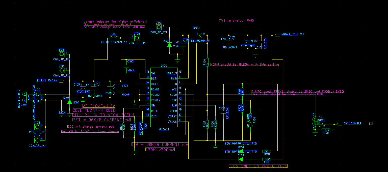
We have a design with the MP2659 and are having some issues. I have pasted an image of the schematic here:
The MP2659 is fed by a boost regulator with an output of about 19-20V, and not pictured on the schematic are the output capacitors, mainly 470µF low ESR electrolytic, along with a 10µF and a 47µF MLCC. Then as you can see in the schematic there is another 47µF low ESR electrolytic and a 1µF MLCC.
After the MP2659 is a battery protector/balancer IC, but it has been shorted to make sure it isn’t causing the issue. The battery pack is a regular 4S Li-Ion pack.
The issue we’re having is that when the MP2659 starts switching it pulls current from the battery and raises PMID and the input voltage by a bit. This seems to be absorbed by the 23V TVS on PMID,
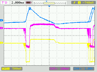
I captured it on an oscilloscope, but it doesn’t seem like I can post more images right now. I’ll try posting it in a reply or edit or something.
Channel 1 is the battery current, channel 3 is the AC-coupled battery pack voltage and channel 4 is the AC-coupled PMID. This seems somewhat strange. Quite a lot of energy is wasted in the TVS, so the battery doesn’t even charge fully when the current is limited.
The input inductance should be fairly small as the boost regulator is right next to the MP2659 and there’s a lot of bulk capacitance.
Any ideas on what the issue is?
Here’s the oscilloscope trace:
Hi Gabriel,
Does this still happen with input coming from bench supply instead of the boost converter?
If so, you can monitor the input current to check if this aligns with how much output current the boost converter can support given that has a limited switch current.
Best Regards,
Yu
Hi!
It’s actually a bit bizarre, it doesn’t happen repeatedly with a bench PSU until I set the current limit incredibly low. However, it does happen once when it starts switching. The boost regulator is a PAM2423 with a switch current limit of 5.5A. It should be capable of pushing out about 500mA or more at the input/output voltages we use. The boost regulator of course stops switching when the MP2659 kicks the input voltage up. I’m guessing the PAM2659 notices the voltage drop and aborts the charge.
So as I can see it I should do one or more of the following:
-Increase input capacitance to deal with the peak
-Increase boost regulator output voltage to give more headroom (though this would hurt efficiency)
-lower VDPM on MP2659 to stop it aborting the charge cycle.
As far as I can see the MP2659 doesn’t have a soft start functionality to stop the initial kick. I’m also not sure if lowering the DPM voltage would actually work. It’s not supposed to stop the charging completely until it reaches 0.2V. I guess I’ll start with increasing the capacitance, then I’ll see what happens.
Any other ideas regarding what to try?
Raising the input capacitance doesn’t really help from what I can see. I added another 2x330µF. Basically the same thing happened but slower.
I think it used to work better before as well. The datasheet does warn against hotplugging source voltage or the battery, both of which happen. But I believe we added the suggested protection circuitry to deal with the spikes. I can try with another board, but we can’t exactly have this happen with final hardware. Is it possible that the IC is damaged?
Sorry for bumping thread. But we have same problem. What was your final solution.
Hi!
A couple of changes seemed to mostly mitigate the issue. There is always a bit of a kick when input or output is connected or disconnected, and also when it starts. We added heavy TVS diodes to clamp input, output and the PMID node. They really only need to clamp at voltages where there is risk for damage.
Then we replaced the boost regulator at the input. A better one with improved regulation stabilized the input voltage. The MP2659 seems to be very sensitive to input voltage fluctuations, and I’m not sure it deals with them the right way. The input DPM and input current limit functions do not work as well as I hoped. It seems to go into some kind of fault mode and just let the inductor do what it will with the stored energy.
So I would recommend experimenting a bit with your source and see if you can stabilize it.
Good luck!