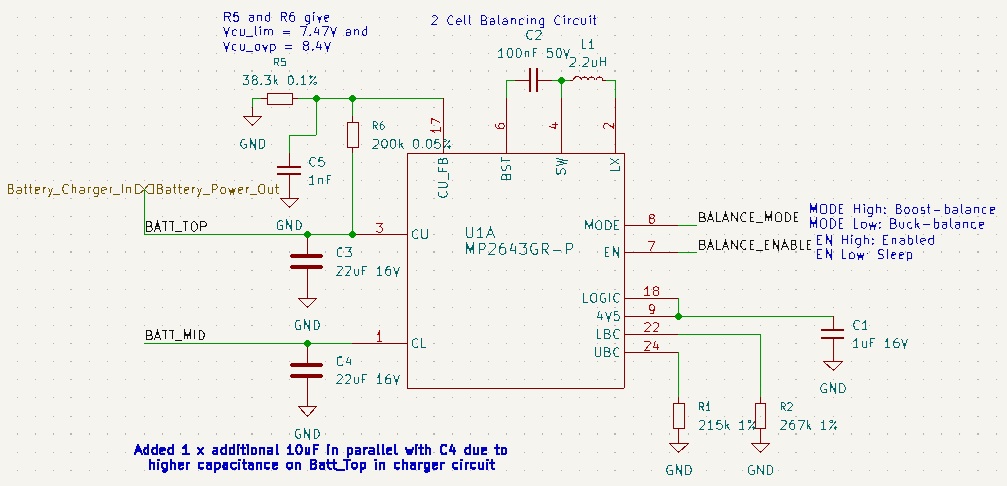
My MP2643 circuit will buck balance fine but will not boost balance when I set the balance mode and enable pin high.
Initially, when I tried to boost balance, the large 22uF capacitors would squeal audibly. Now it is silent but it draws current from the top cell (~900mA) and the lower cell (~185mA) and gets quite hot. I’m assuming this particular chip is damaged but obviously there is a problem I need to fix. I am running 2 x 18650 cells as the battery for testing but my product will have a 2S4P pack eventually. The cell voltages were 2.75V and 3.01v when I tried to boost balance. The cells feature an OV/UV/OC protection circuit internally.
Thank you for posting your question in the MPS Technical Forum.
I have reviewed your schematic, and overall it does not seem to have any outstanding issues.
The fact that you hear noise from the caps, and the IC getting hot may be an indication of overcharge.
Some questions I have are:
Are you monitoring the voltages of the cells while balancing?
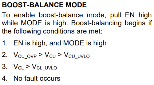
Also, have you confirmed that these condition for boost mode are met?
Since posting originally, I have replaced the IC and modified the values on the CU_FB pin to match the development kit schematic.
I originally designed a circuit with a number of opamps and comparators to drive the ENABLE and MODE pins. The circuit worked well at DC but as soon as the balancing started, excessive noise on CL and CU pins would upset the circuit and cause it to oscillate the MODE output. I tried more filtering etc but I will likely replace it with a microcontroller and 2 opamps. The balancing needs to be coordinated with a battery charger as well.
For now, I have tied the ENABLE and MODE pins to a 3.3V power rail to provide known inputs for the MP2643. I am periodically checking the cell voltages with a multimeter. During Boost balancing, VCU is 6.485 and VCL is 3.260V. These voltages are within the limits you mention.
When the circuit first powers up, the currents are flowing OUT of the top AND bottom cells in the batteries. The current for the bottom cell then ramps down and changes direction over say 5 seconds. Once they settle, the currents are 1A OUT of the top cell and 125mA INTO the midpoint between the cells which seems to be the wrong directions to me. I would expect the currents to be closer in magnitude and the opposite directions. I have confirmed the MODE and ENABLE pins are both high. Once the currents settle, the capacitors start to squeal audibly.
In Buck Mode, the currents are 1.292A OUT of the top cell and 0.638A INTO the bottom cell which is what I would expect for current direction. Are these magnitudes reasonable? Also, the chip temperature reaches 95C which seems excessive but no capacitor squealing.
All I need is the buck and boost balancing to work separately as the PCB is getting redesigned anyway. I just need to make sure I don’t carry over any mistakes to the next version of the PCB.
Found 4.5V output measuring at 4.33V which is out of specification (4.4V minimum from datasheet). Also found after <1min of attempting to run in boost mode, 4.5V rail starts dropping to 0V and then back to 4.33V periodically. I suspect over temperature problems as chip gets to >100 degrees C. Checked for shorts between high power pins (Pins 1-5). No Shorts. Checked all pins for shorts to ground and adjacent pins. No shorts. Triple checked soldering of chip- ok.
@Edgar.FAE I disconnected the battery charger circuit and as much other circuitry as possible to prevent any interaction. Symptoms are still the same. I have some 1uH inductors on order as per the development kit values.