Hello,
I have recently built out a PC-board containing the MP2639AGR-Z in order to charge two 3.7V 2.2AH 18650 Li-ion cells (in series) used with a DC-DC converter. I have gotten the device to power on however, the time out error light blinks and the batteries are not charging I double checked the schematic with the one given with the reference board (with new RT1,RT2, input current and charging current limiting resistor values) and can not seem to find where the problem is. the new values for the resistors are:
RT1 = 2.67k ohm, RT2 = 7.5k ohm, Riset = 191k ohm, and Rilim = 120k ohm. The NTC thermistor used is from visay BC components (part # NTCLE413E2103F 102L), a 10k +/-1% thermistor with a R_NTC_cold
of 3536.2, and a R_NTC_hot of 27348. Any help on the subject would be greatly appreciated.
Hello,
I had RT1, and RT2 swapped on the PC-Board, I switched them around and no longer have the NTC/timer error. however the IC chip still will not charge the batteries it lights up the charge status light (indicating a fault i believe). any suggestions on what the fault would be?
-Jeremy Sklute
Hi Jeremy,
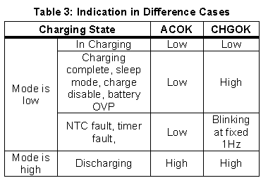
May I have a look of the NTC pin resistor divider connection? According to your NTC resistance under HOT and COLD, I think 2.67k ohm high-side divider (connected between VNTC & NTC) resistance and 7.5k ohm low-side divider (connected between NTC & GND) resistance should not result in NTC/Timer fault. Or you could check if the TMR capacitor is soldered on or not. Also, you could have a look at the voltage of NTC pin when NTC/TIMER fault occurs.
Secondly, if your design follows our EVB SCH, then CHGOK is low during charging process and the charge status light will be lightened. It is not a fault. When the battery is fully charged, CHGOK will be high and the light will stop as well.
BR,
Lea
Here is the schematic for RT1,RT2 and the thermistor (RT1 = 2.67k ohm, and RT2 = 7.5k ohm)
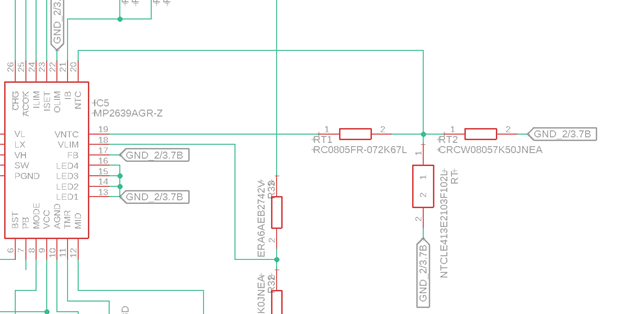
-Jeremy Sklute
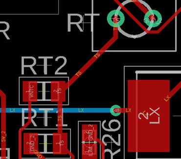
I figured out why I had to swap them around in the PC-board; the part names for those two resistors had been misplaced when the PCB was initially laid out; meaning that the RT1 label was put above the actual RT2 resistor, and the RT2 label had been put over the actual RT1 resistor, as is shown in the image below.
I have gotten the IC to at least try to charge the batteries after fixing a bad connection on the Iset resistor (R26), however now the charge status light will randomly blink and every time it blinks, I see a momentary rise in the voltage of the batteries being charged. I believe this is due to a bad connection between the usb port and the PC-board. This is because I was able to get the IC to correctly charge the batteries when I connected the PC-Board directly to a 5V DC power supply, as opposed to using the USB port as had been done previously. Thanks again for the help on this subject and I believe this problem has been solved.
Sincerely yours,
-Jeremy Sklute