Hi, we received our first prototypes of our phone PCBs and we are having an unexpected issue with the charger IC.
The IC we are using is the MP2625B. We are using single LiPo pouch cell. The cell has its own typical protection for undervoltage (it opens a high side mosfet when discharges below 3V).
CC in the IC is setup at around 900mA.
The input to the charger is VBUS (5V).
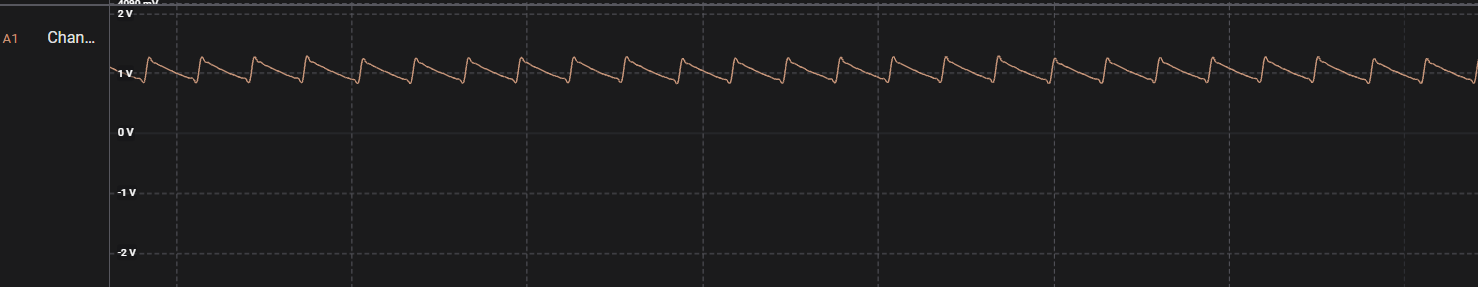
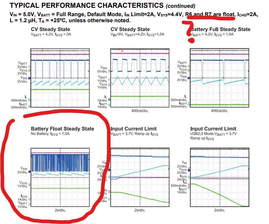
(1) If when I plug VBUS to 5V, the cell is disconnected, the chip will put around around 1V in BATT pad (this is unexpected, I was expecting CV voltage 4.2V in this case).
(2) If when I plug VBUS to 5V, the cell is connected, it will enter in CC and I’ll see battery voltage in BATT pad. If then I unplug the cell, I’ll get CV voltage in the BATT pad as expected.
The issue is that (1) is very normal for our product usage, as when the battery discharges, the cell protection will open the cell mosfet. When the user plugs the phone to USB, the charger IC should output 4.2V to reestablish cell and start charging.
Currently with this behaviour, the cell will keep the MOSFET open and won’t charge.
I need urgent help, as I have been trying to solve it for the whole week, I couldn’t and need to give a solution to the CEM for fixing it.
Thanks!!! Best.
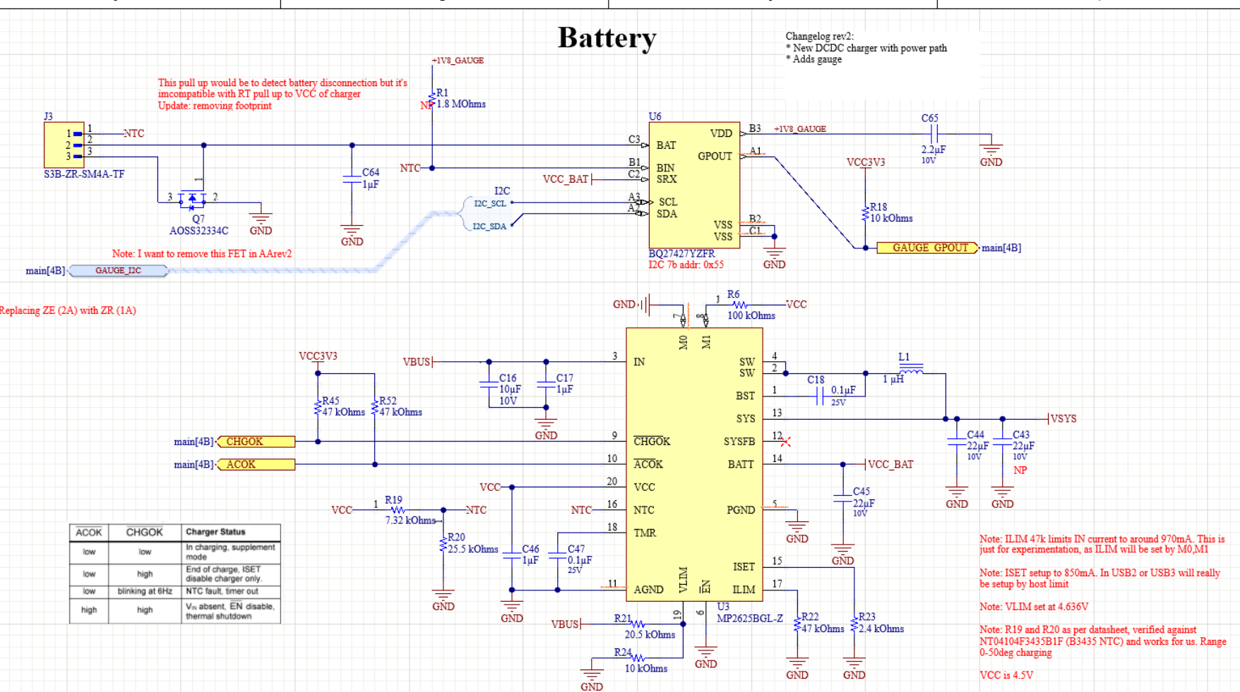
wrong in the setup of the chip