Hi. I have a problem with the over-discharge protection of MP2617. I use MP2617GL to design a battery charger and system load management in 2 versions of 5v-input and 12v-input.
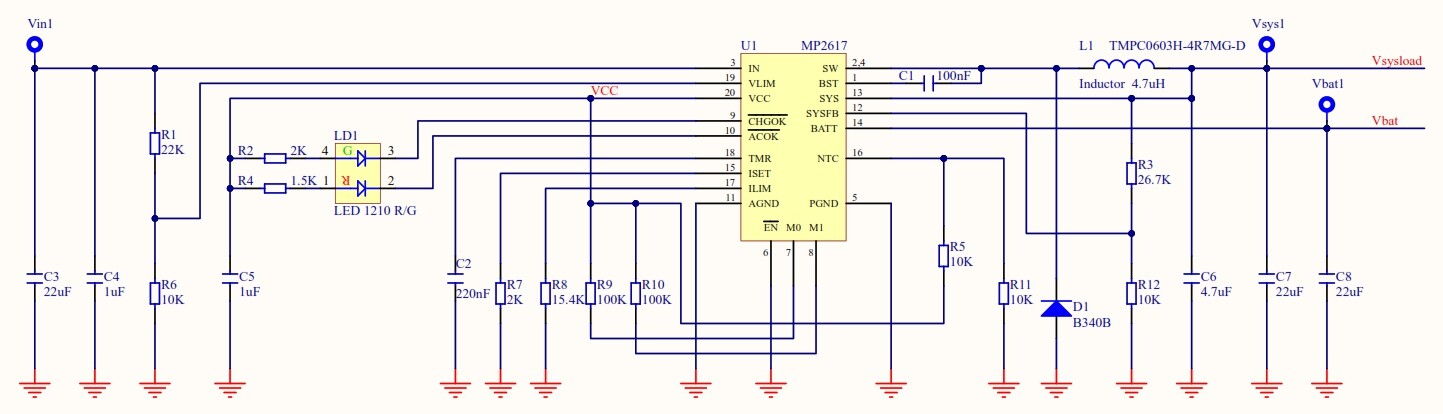
I use a 5000mAh Li-ion battery with a design specification of 1A charge current, 220nF capacitor for TMR that results in about 68min for trickle current time, and other settings shown in the attached schematic picture.
In a scenario test, I disconnect the input and charger supply load from the battery when the battery is full charge. When the battery is discharged, the charger disconnects the battery from the load. I left the battery in this situation for about 16h so the battery is fully discharged.
when I connect the input supply, in the 5v-input version the charger works properly, and in the trickle charger situation, the charger charges the battery.
But in the 12v-input version, when I connect the input supply, the charger doesn’t charge the battery and the system load voltage is zero. one time the ic charger is damaged.
I test this situation for 2 charger versions (5v & 12v) with one battery and everything is similar.
Thanks for your help.
Hello,
Apologies for the delayed response.
For the 12V case, would you be able to elaborate more? Is the battery discharged and then you connect input as well as load and it doesn’t charge? What is the test condition for when it was damaged?
Additionally, for the 12V input, was R1 changed so the input clamp voltage Vlim is around 1.5V?
Best Regards,
Yu
Hello,
Thanks for your support,
The R1 and R6 of the Vlim pin are the same for both the 12v input and the 5v input versions.
The problem is about the over-discharge battery condition. For the 12v input version, I disconnect the input and let the battery supply the system load. This situation continues to the situation where the battery voltage drops to 2.5v and IC charger disconnects the battery from the system load. Then the battery remains in this condition for about 14 hours and then when I measure the battery voltage it is 0v!!!. I guess the protection circuit inside the Li-ion battery disconnects the battery port. Anyway…, when I connect the 12v input source of the charger, the IC does not charge the battery. the system load voltage is 0v and both LEDs are ON but I think the IC charger detects a short circuit condition and does not charge the battery but there is no hard fault condition for the LED (the LED does not Blink). This situation remains for 3 hours when I connect the 12v input but IC does not charge the battery and the system load voltage was 0v.
But this problem was not seen for the 5v input case.
Hello,
I am looking into this and will get back to you.
Thank you for your patience.
Best Regards,
Yu
Hello,
Thank you again for your patience. We would like to know more information to see what is happening.
How are you measuring and seeing 0V? Because the battery voltage drops to 2.5V or below, the battery pack has turned off its internal FET. Otherwise this big capacity battery won’t drop so quickly, the quiescent current from VBATT in MP2617H is small.
How many MP2617H do you have?
For the case where the IC charger was damaged, how did you come to this conclusion? If you
decrease input back to 5V, does it work?
Best Regards,
Yu
Hello, Thanks for your help.
I measured the voltage of the Vbat pin, and it was 0v after about 14h that the battery had been disconnected from the system load. After that, the battery voltage dropped to 2.5v or below the IC charger disconnected the battery from the system load, and the battery’s voltage was 2.5v. But after about 14h, the battery continued to discharge weekly, and the internal FET in the battery disconnected it. So, I measured 0v from the Vbat pin in the circuit. I have 2 MP2617GL and two circuits I designed (one for 5v input and the other for 12v input).
When I connected the 12v input to the circuit, IC didn’t charge the battery because the sysload voltage was 0v again, but 2 LEDs on the circuit were ON. I also waited for 3h, but nothing changed, and sysload voltage remained at 0v. After trying to connect and disconnect the input voltage multiple times, I found that the IC charger was damaged. Because I changed the discharged battery with a new battery, and the IC charger didn’t work.
Yes, when I decreased input back to 5v, the IC charger worked, the battery was charging, and sysload voltage was 3.6v for trickle mode.
In the case you decreased input back to 5V and it worked, was it using the IC charger that was damaged?
No, I used another circuit that I had. I tested this scenario twice, and both times, when the input was 12v, I had this problem and changed the damaged IC with a new one. But the problem repeated.
Just want to make sure, when you apply 5V input to the damaged IC, does it still not work?
Yes. Exactly. When I applied 5v input to the damaged IC, or even I changed the dead battery with a new one, It was not working.
Hello,
Thank you again for your patience. Have you tried this on our evaluation board?
You can test out 5V and 12V input case with your battery on the EVB. If that works, it is probably a design issue and not the chip itself. After, you can modify the EVB to replicate your design.
Best Regards,
Yu