Hi There - I am currently testing my circuit’s NTC window and am having issues with CHGOK blink function. I can see that the charge is suspended if the thermistor exceeds our programmed limit (~45C), however, CHGOK does not blink as it should. It remains LOW as if it was still charging. We do have the timer disabled, would this cause this issue? What else could cause this issue?
Thank you,
Lionel
Hello again Lionel, apologies for the delayed response. I am happy to see that you and your Team at Kickstart Design are developing with the MP2617H.
Disabling the timer shouldn’t have a direct effect on the CHGOK function. But the timer does manage charge cycles and some safety features. It shouldn’t prevent CHGOK from blinking in response to changes in temperature.
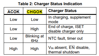
However, the CHGOK signal is directly influenced by the Over-Temp protection logic. When the temperature exceeds the programmed temperature threshold, the IC suspends charging where CHGOK remains low and should blink to indicate that charging has suspended. Since you are not seeing any blinking, please verify the following:
-
Ensure that the termistor is calibrated to activate the over-temp protection to your desired point. If this is set too high, charge may suspend but the IC may not register a fault condition. It appears that you have things connected correctly.
-
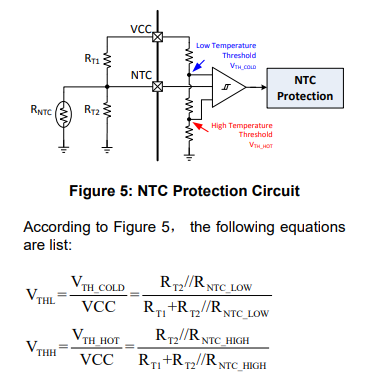
Double check that RT1, RT2, and RNTC are all configured to your target voltage window thresholds to also ensure your thermistor is also within range (page 20).
-
If you are reading from any registers or some form of external monitoring on the registers, ensure that status flags are properly cleared after temp returns to normal. If a fault condition is latched, then CHGOK may stay low. Try forcing a reset on fault conditions if needed for testing purposes.
I noticed that your design is influenced by this typical application schematic in the MP2617H datasheet. Your schematic appears to align well with this.
Just wanted to also verify what exactly the input voltage you are working with here as well. I noticed that you had designed in a 1.5uH inductor which is the minimum inductance for a 9V input. Is this the case with your design?
I know this was a lot to send out at once, but I look forward to your response.
Best,
Krishan
Hi Krishan,
Thanks for the detailed reply. To answer your question, we are working with a 5V input supply. We ended up adding the Ctmr capacitor anyways, which seemed to resolve the issue altogether. I’m not sure about the logic behind this, but it worked.
Now, another problem we are seeing is the rate at which CHGOK blinks seems to change depending on the size of the capacitor selected fot Ctmr. For example, we have tried 0.1uF capacitor and 0.57uF capacitor. With the 0.57uF capacitor, the blinking is slower than with the 0.1uF. The datasheet states 6Hz blink rate, which did not align with either of these selections. I am assuming the blink rate (Hz) is related to Tcycle in some way. Is this correct? If so, what is the relationship?
Thanks!
Hello Lionel,
Apologies for the late reply on this follow-up.
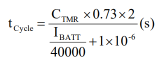
You are correct with your assumption that the blink rate is related to t(cycle), as this would be the period of the 6Hz where t(cycle) = 0.1667s. Based on the forumla, a higher capacitance would lead to slower blinking as you observe.
You will need to verify and measure Ibatt in your system in order to verify the capacitance for Ctmr such that your LED will blink at 6Hz.


