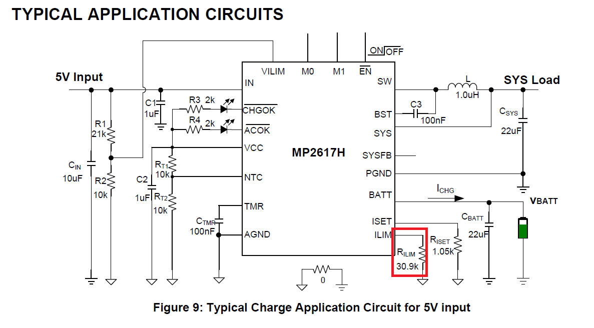
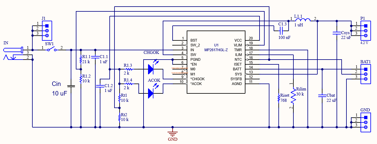
I have design an MP2617HGL-Z charging circuit to charge a 3.7V Li-Ion battery, I followed the design schematic as closely as possible, I used a 768 Ohm resistor to program the charging current at about 2.5 A, I also used a 30 kOhm to limit the input current, the problem I have now is that when I connect the battery through an ammeter to measure the charging current, it reads 100 mA for about 2 seconds then stops, what could be the possible causes for this issue?
There are two choices here, the ammeter or the input resistor.
If you really put a 30k resistor in series with the input I am shocked that you can actually charge at all. Does an input current limiting resistor appear in the reference schematic?
Secondly if the ammeter has significant resistance the voltage drop across the ammeter could trick the IC into thinking the battery is fully charged.
Measure the current on the input side, just hook the battery cleanly to the IC. If you want to measure battery current uses a clamp on type ammeter ( not super accurate) of a low value resistor and a good voltmeter.
Thanks John for the reply.
No I did not put a 30 kOhm resistor on series, I meant the R ilim that is on the typical application, which is used to limit the current, I attached the picture from the datasheet to show what I mean, I will also attached a picture of the my whole design schematic, I really appreciate the help.
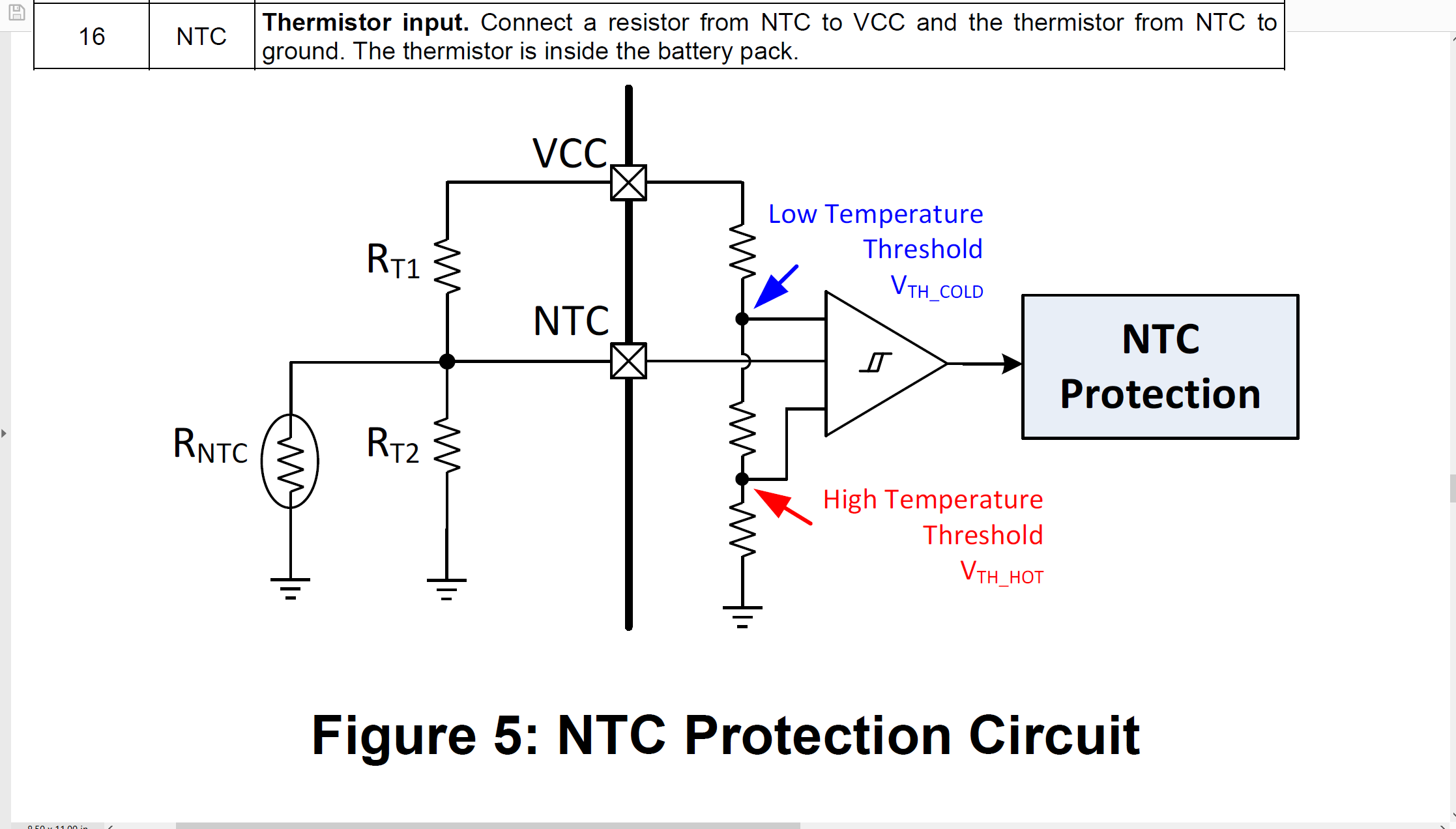
Well what about the NTC? In the ref schematic they just insert a fake signal into that node with 2 10k resistors. You have the 10k external divider in parallel with the internal 10k NTC in the pack so effectively a 5k/10K divider 0.33 of Vcc right on the too hot detection threshold?
On the NTC pin, I followed the NTC protection circuit design on the datasheet which is attached below. I also attached the NTC pin description from the pin function table.
So is the design incorrect, can I cancel the NTC functionality?
I am just some guy on the internet, my observation is, that with a 10K NTC and Rt1 and Rt2 at 10k the voltage at the NTC pin will be 1/3 of VCC which is right at the too hot threshold. Can you measure the voltage at the NTC pin to see if you are super close the the too hot threshold?
The text you cited implies that with the pack NTC you don’t use Rt2 ( makes sense to me) and with no pack NTC you feed fake infor to the NTC pin to prevent it shutting down.
I think I see what you’re saying, so I should remove RT2 since the internal (RNTC) is replacing it!
That is my guess. Poorly worded datasheet