We have an application powered by a single 3.7V 900 mAh LiPo cell. The cell is charged by a MP2607 with a USB-C power source. The system is designed to power off if the cell voltage drops to 3V and there is no USB power available.
Ichg is set to 445 mA with a 5k1 resistor. Charge timer is set to 2.28 hours with a 1 uF capacitor. Both status pins are connected directly to digital input pins of a PIC microcontroller, with 4k7 pull-ups to the Vsys pin of the MP2607
Testing shows that some cells discharge to ~2.76 V before system shutdown. When USB power is re-applied the cells don’t charge. No current flows into or out of the battery (measured with a sensitive ammeter) but the current drawn from the USB power supply is ~100 mA higher than the system normally draws when not charging the battery
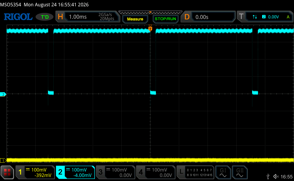
Seen on an oscilloscope, one of the status pins is oscillating. STAT1 remains low, but STAT2 is high for ~3.6 milliseconds, then low for ~180 microseconds (see attached screenshot).
Thank you for posting on the MPS Technical Forum. I have two ideas for what may be happening:
Depending on VIN, your ICHG may be too high. With ICHG being 445 mA, ISYS (100 mA) + ICHG > 490 mA (the USB-mode switch limit for the MP2607). In USB mode, system load takes priority so charge current may be getting squeezed.
Does there happen to be a protection board on the 3.7V cell? Since STAT1 remains low, STAT2 is reporting “Charging” followed by EOC. The EOC threshold is <=10% Ichg. It could be that the system is seeing less than this amount in the charge window, after driving the charge FET and expecting a larger current. This would then trigger EOC again in the cycle. This leads me to believe that a potential protection board/component may be limiting all of the cell’s current due to overdischarge protection.
Could you please try reducing the charge current to 300 mA (RCHG = 7.5k) and informing me of the result?
The normal current consumption of the device is less than 30 mA, so we don’t think that we are exceeding the 490 mA limit for USB charging. Peak demand does approach 100 mA for short periods of time if the device receives an incoming message
The battery pack we were using didn’t have any protection, so our design incorporated a TI BQ29737-based protection circuit between the charger and the battery. This had an Under-voltage protection threshold of 2.80 V and an Over-voltage threshold of 4.25 V.
Since my original post, our client has swapped battery suppliers and they are now using a 900 mAh Lipo battery that has a protection board inside the pack. Experimentation suggests that the Under-voltage threshold for the protection board is 2.40 V, which is much lower than the BQ29737. This also seems to be much lower than the frequently-quoted value of 2.80 V minimum voltage for a Lipo cell.
As a result of the battery change we have removed the BQ29737 from the battery circuit and have not seen the strange behaviour that caused the original post. This would seem to confirm your belief that the BQ29737 was the source of the problem.
I’m glad to hear that the problem has been resolved. Please do not hesitate to reach out again if another issue arises related to this project or a separate concern. Thank you for choosing MPS!