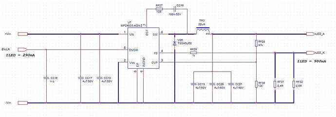
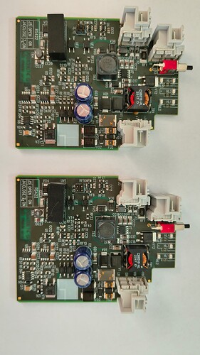
Hi, I have designed board with MP24833-A (buck converter) according to datasheet. I have set output current 900mA. A have two identical boards with this same level of output current, of course with the same supply voltage and other condisions. If I need decrease output LED current (to 270mA) help to EN/DIM input (in analog mode), in one case I have to set 876mV on EN/DIM input, in the second case I have to set 911mV on EN/DIM input. In other words - if I set 876mV on EN/DIM input on both two identical boards, one provides output current 270mA, the second one provides output current 220mA. Is this inaccuracy a normal feature of MP24833-A?
probably is that bad, I would bet you a PWM scheme would have less variation unit to unit.
I did some control measurement, see chart:

It looks, both two boards work identicly only without EN/DIM analog regulation. The greater regulation, the greater inaccuracy.
Any idea, where is the problem?
My bet is the “problem:” is with the chip. There is no particular spec for the accuracy of this function and it isn’t that accurate. It is fine if you have just one of them and adjusting until the brightness is where you want. It is less fine if you want 10 of them all at once to be match within 5% or something. Using the PWM function should work fine as the full current setting is accurate unit to unit.
It is probably some base emitter junction pulling down on an internal node, so you have the beta variation, offset variation, and temperature variation of that.

