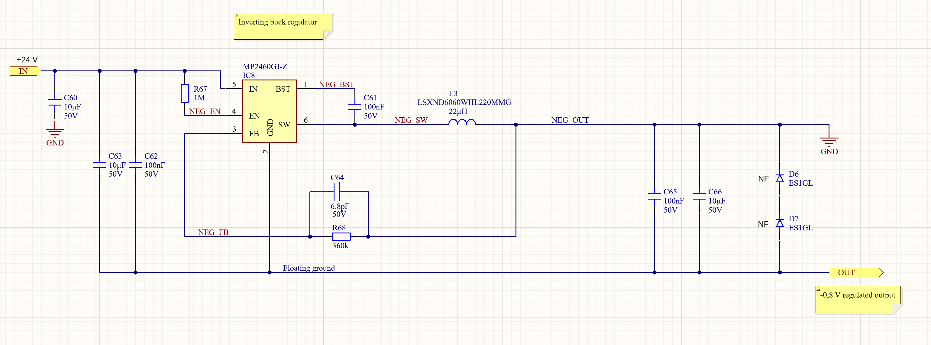
I am trying to use an MP2460 regulator IC to convert +24 VDC into approximately -1 VDC but I’m having some problems getting a negative output. The regulator is connected in an inverting buck-boost configuration as per the schematic below. Diodes D6, D7 are not fitted.
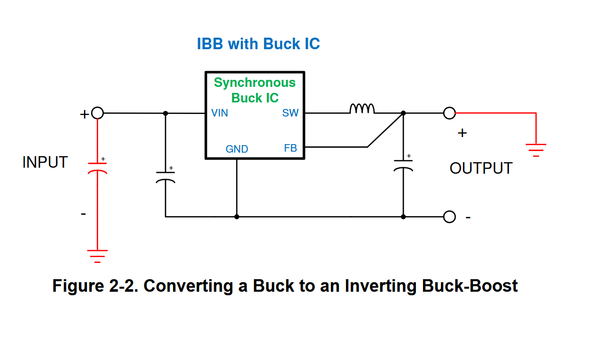
When measuring the output voltage, I connected the negative lead of my multimeter to the node marked “GND” and the positive lead to node marked “OUT”. My multimeter reads about +0.56 V. Shouldn’t the node “OUT” be at a lower potential than GND as this example shows?
Hello! Thank you for reaching out to the MPS Forum and I’m glad you’ve chosen our part for your application. I believe you are on the right track with the inverting buck-boost configuration. However, I noticed in your schematic only has one feedback resistor in the network and it does not reference the output voltage node. The app note where you found the block diagram should give a more detailed explanation on how to connect it. You can also refer to the MP2460 datasheet to calculate the correct values for a 1V output voltage. I hope this helps!
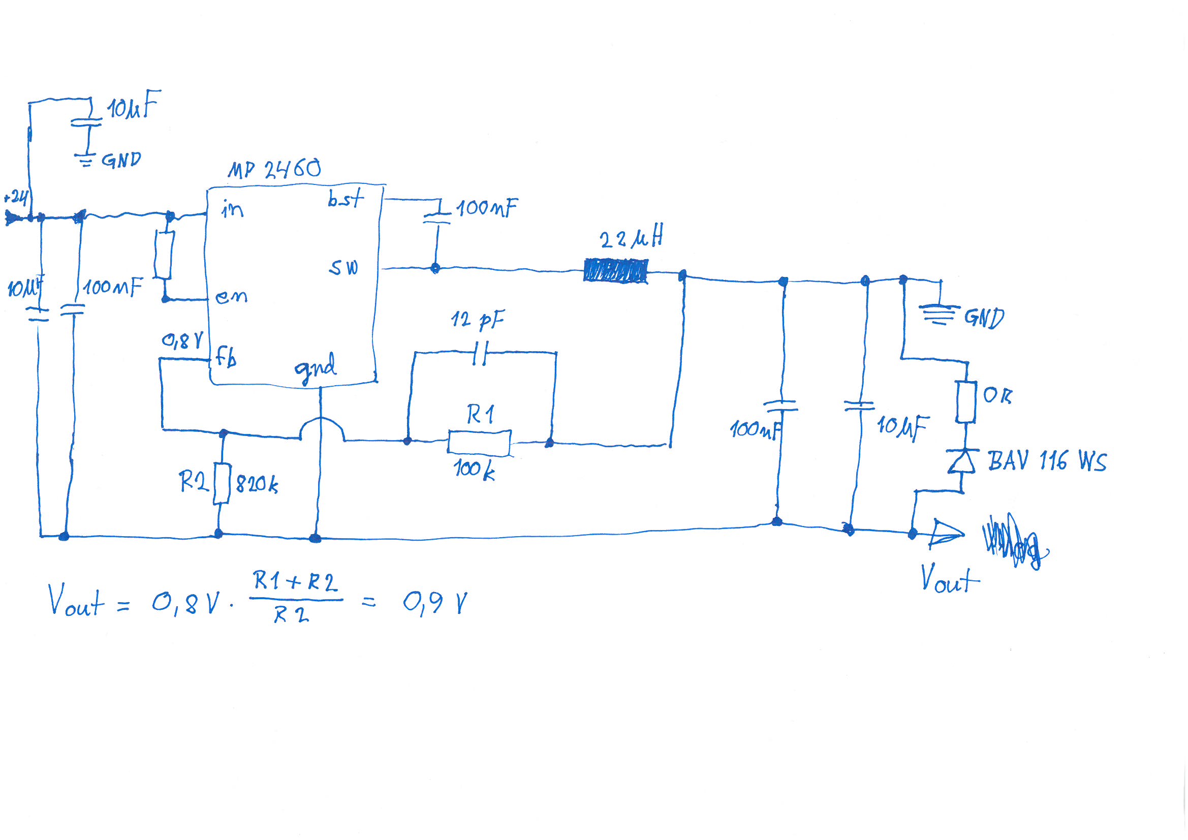
Thanks for your reply and your hints. I modified the original circuit by adding/changing the feedback resistors and a clamp diode. Unfortunately I did not have a 6.8 pF capacitor. Please see the revised circuit below.
With these changes, I noticed the output still stays at +0.55 V after power-on when I immediately switch the input voltage from 0 V to 24 V. I use a lab power supply which ramps its output from 0 to 24 V in about 20 msec.
But when I slowly increase the input voltage from 0 V to 5.4 V, the output ramps up from 0 V to about 0.5 V. After increasing the input further from 5.4 V to 24 V, the output suddenly flips down to a constant -0.89 V. This is very close to what I expect the output voltage should be.
My finding so far is that the circuit has problems starting up properly from quick application of 24 VDC input. Any advice?
Thanks!
ps. We have three other mp2460 (positive) regulators on the same board. The other mp2460s are supplying +3.3 VDC, +5 VDC and +24 VDC supply rails and are working without any problems.
Hello, thank you for updating me with the new issue you are having. I have a few questions that will help me diagnose potential issues. My main concern is that your clamp diode may not be working properly, since once it is installed the Vout node should not be higher than the GND node.
Would you be able to provide the output current spec?
Is the -0.9V rail paralleled with any other voltage rails on the board?
Have you noticed the diode feeling warm during operation at all?
Hello
Turns out the BAV 116 type is a bit special as it has higher than normal forward voltage. Data sheet mentions typical Vf between 0.9 V and 1.2 V.
I replaced the clamp diode with BAT 46, which is a Schottky type. This seems to have solved the problem as now the circuit starts up without any problem and provides a stable -0.9 V output.
Output current spec would be approximately max. 100 mA.
The -0.9 V rail is not paralleled with any other rails. It is used as a negative supply rail for op-amps.
I’m glad to hear that your circuit is working as intended. If you have any more issues, do not hesitate to reach out! Thank you again for choosing MPS.