Hi, I am looking to use MP2459GJ-P buck regulator to create a +24V output from +48V input, and also a +5V output from a +24V input. The output current requirement is 0.2A.
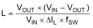
Using the inductor equation provided in the formula, I get values around 420 uH and 140 uH respectively for the 2 circuits. These are very large inductors.
When using the online tool, here DC DC Designer Online - Design Tools - Design, it gives me a value of 47 uH for both circuits. However, it seems possibly that the inductor value is maxing out at 47 uH. When I adjust the ripple current %, the inductor value remains at 47 uH. I would expect the inductor value to decrease with a higher ripple current, and vice versa.
Could you please let me know what is the correct inductor value to use, and whether I can create the supplies I need with this part. It seems to me that the Vin to Vout difference is too great for the amount of current we need, though everything is within the recommended operating specs per the data sheet. Supply Voltage VIN … 4.5V to 55V
Output Voltage VOUT …0.81V to 0.95×VIN
Thank you! Please let me know what other information I can provide.
Jeff