Hello everyone,
I am currently working on a power supply circuit using the MP2451 with following parameters:
Vin_range: 4,6 - 27V
Vin_optimal: 12V
Iout_max: 150mA
Iout_min: 3mA
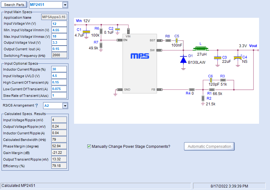
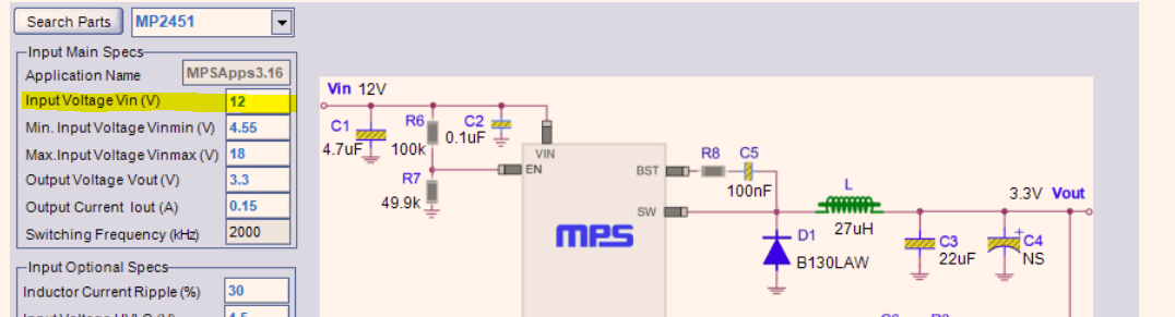
The schematic proposed by MPS DCDC Designer is presented below:
see Pic.1
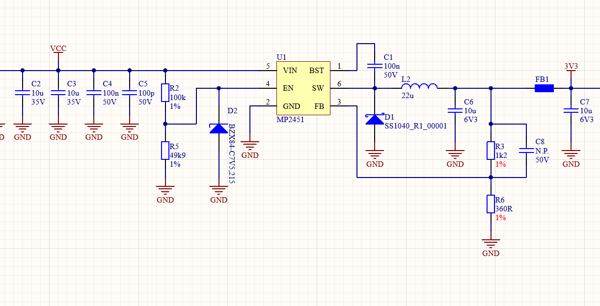
The schematic used is presented below:
see Pic.2
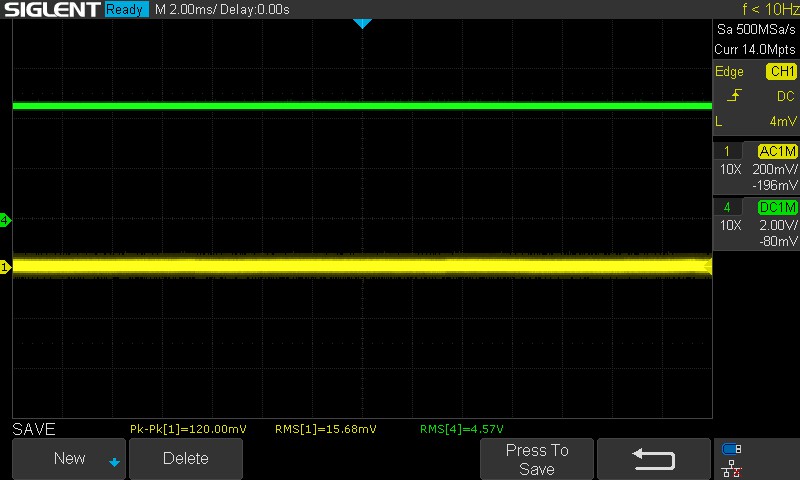
Everything works fine except the under voltage protection. I have a voltage divider at the Enable input, therefore, according to the documentation, the IC should operate from a voltage of 4.6V (1/34.6 = 1.53V). The trailing threshold is around 0.7A, because the converter shuts down at 3.9V. (1/33.9 = 1.3V). In practice, however, it is different, when the input voltage is within the trailing threshold range (4.6-3.9 V), the converter randomly turns off and on. See oscillograms below:
Channels
- Green - input Voltage (DC)
- Yellow - output voltage ripples (AC)
Conditions - I_load = 150mA
see Pic.3, Pic.4, Pic.5
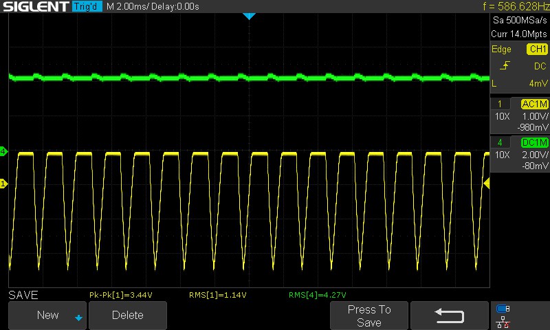
Channels
- Purple - SW node
- Yellow - output voltage ripples
Conditions - Vin = 4.27V
- I_load = 150mA
see Pic.6
I have already tried many things:
- changing the values of the feedback resistors to those proposed by the MPS Designer by adding compensation.
- changing the input / output capacity.
- adding small value MLCC capacitor to EN pin.
Unfortunately, the result is still the same. I only improved Vout when I decreased the value of the feedback resistors, now I have a stable 3.3V across the entire input voltage range. Unfortunately this did not solve my UVP problem. Does anyone have a suggestion?