Hello!
My MP2393 chip has 5.2 volts at idle, and under a load of 7.5 Ohms, which is about 800 mA, the voltage drops to 1 volt. It looks like it’s dead.
Please tell me an analog of the MP2393 chip, from the same series.
The supply voltage is at least 20 volts.
The current is at least 2 amperes.
So that you can replace pin to pin without replacing the strapping.
The MP2393 chip costs us some exorbitant amount of money and the delivery time is 3 months.
I would suggest the MP2393. There are many reasons a chip in a circuit might not work, some component could be misstuffed, some components could be underdesigned the layout may be poor. I find EVAL boards very helpful when looking at a new chip. It would be semi miraculous if you had a pin for pin analog power replacement. Did you hot plug this from a high voltage?
Hello,
Sorry to hear you are experiencing some issues with the output of the MP2393. If the part was dead we would not see an output voltage at idle. I agree with JShannon, there can be many factors that can contribute to a converter behaving unexpectedly. You can reference our EVAL boards which include typical applications, layout guidelines, and BOM. See eval board link here:
EV2393-TL-00A | High-Efficiency, 650kHz,3A, 24V. Step-Down ConverterEvaluation Board | MPS
Unfortunately, MPS does not have aby pin to pin replacements for an analog part. If you are looking to replace your part, I can suggest the MP2338 or MP2330. These have the same package, pin compatible, and have similar performance. External components may need to be changed.
Can you share SCH and waveforms you are seeing? Switch node and Vout with no load and 800 mA?
Thank you!
You have just given me a lot of hope. At idle I have 5.2 volts, as it should be. When connecting a 7.5 Ohm resistor, this is approximately 800 mA of load, at the output I have approximately 1 volt. This microcircuit is installed in a Sony music speaker, there are 4 such microcircuits for 1.2, 3.3, 5.0, 5.2 volts. The speaker fell and the cover blew off several SMD components around the 1.2 volt microcircuit, I restored the strapping components by analogy with other microcircuits (this is a resistor on pin 5 and a capacitor on pin 7), but I did not notice 1 component (on pin 5 after the resistor there is a capacitor) and I did not have 1.2 volts at the output, I decided that perhaps the problem was in the microcircuit and swapped the microcircuits from 5.2 to 1.2 volts and during the replacement I noticed that 1 capacitor was missing in the strapping of the 1.2 volt microcircuit, I installed it and it worked.
Now when connecting a 7.5 Ohm resistor to 1.2, 3.3, 5.0 volts, the voltage remains stable, but when connected to 5.2 volts it sags.
I will recheck the ratings of the components around the microcircuit, perhaps one of them is damaged.
I am not a professional technician, I am a simple radio amateur, so I do not quite understand what data you are asking from me. I have a small oscilloscope and a multimeter, please tell me on which elements and what to measure to check the microcircuit.
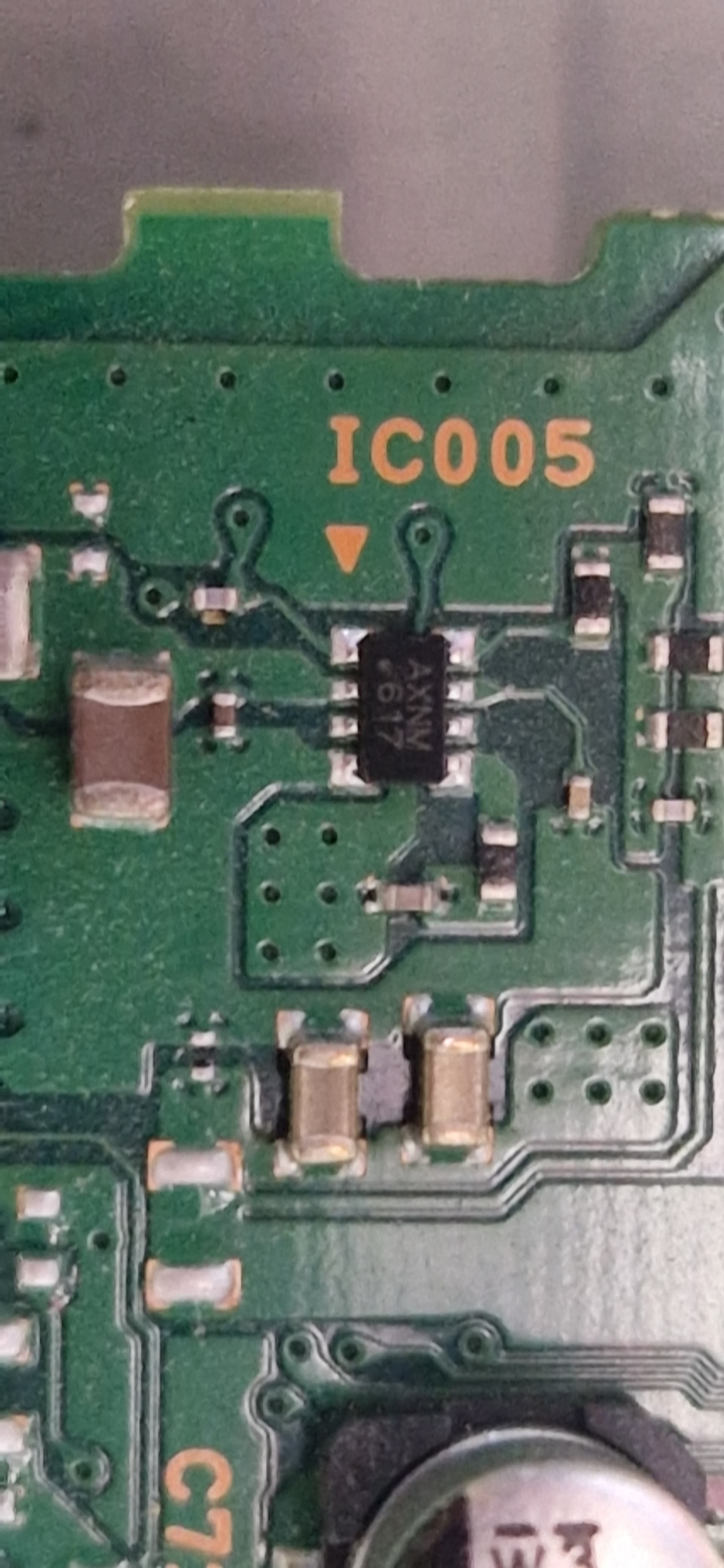
Below I have attached several photos.
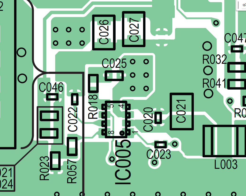
In the photo with IC005, all the components are in place, I just swapped the microcircuits.
I am grateful to you for any help!
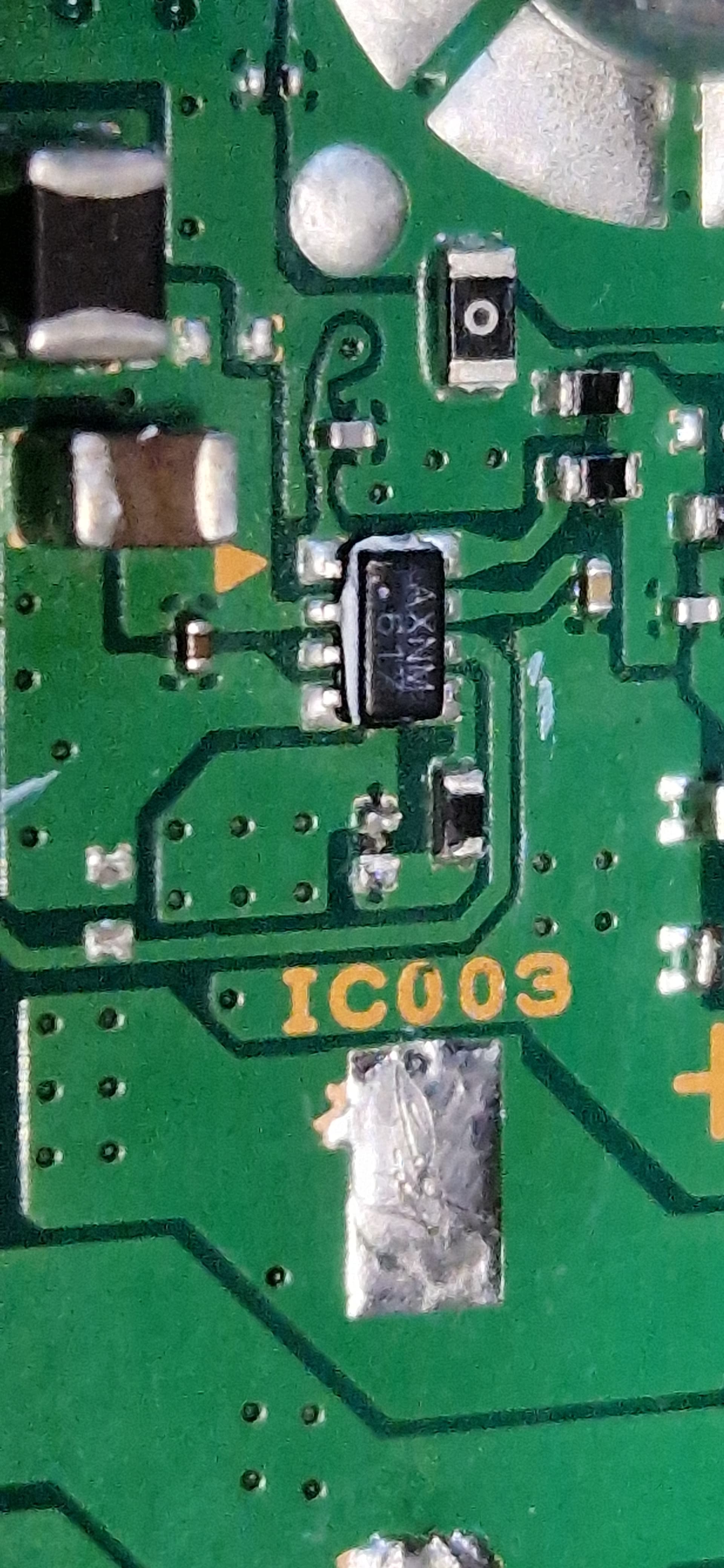
In the photo with IC003, the element that I missed and later restored. This is 1.2 volts.
In the photo with chokes from left to right 1.2, 3.3, 5.0, 5.2 volts.
If possible, I have one more question.
In the photo below there is a missing element, from pin 6 of the microcircuit to ground (pin 4). In the datasheet, to turn on, pin 6 is connected to the power supply with a 604 kilo-ohm resistor, in my case it is the same, only there is also a resistor to ground. On the neighboring microcircuit, which is 3.3 volts, there is the same resistor, I unsoldered it to measure the resistance, but it turned out to be open. According to the datasheet, it should work stably without a resistor with a pull-up to ground, is it necessary to install it and if so, what value should I set? 10 kilo-ohms should be enough, I think. On the 5.0 and 5.2 volt microcircuits, there are no such resistors, since the controller controls the switching on there.
Hi,
Thanks for clarifying and providing additional information. If you have a multimeter, please probe the feedback pin voltage. Since you are swapping by what other parts have populated, it is very possible one of the resistors is not the correct value or has deviated from the expected value.
With an oscilloscope, probe Vout (top of the capacitor connected to the inductor pin furthest from the IC) and Switch node (pin 3) when loading the converter. Additionally, with a multimeter you can probe the feedback network to determine if the values are what are expected. Sometimes a resistor or capacitor could derated such that it dramatically affects the internal control circuitry.
Additionally, when adding the resistor to load the IC’s. ensure it is rated for the proper power.
To address your second question, it is OK to not have a resistor from EN to GND. Adding this resistor will provide a voltage that is within the range of what is needed to turn on the converter. If adding an additional resistor to GND for the EN line, ensure the resistor divider network will provide 1.24V to turn on the converter.
I would highly recommend trying to find a schematic for these speakers as just swapping components may be inefficient. Once you are able to find the schematic, compare with our evaluation modules and suggested part ratings.
Thank you very much for your help!
To exclude the malfunction of the microcircuit, I installed a 5.2 volt microcircuit in place of the 5.0 volt microcircuit and it works fine there, so the problem is not in the microcircuit.
Now I have a microcircuit installed, which was set to 5.0 volts and the voltage without load at the output is 5.2 volts, under the load of a 7.5 Ohm 10 Watt resistor, the voltage drops to 1.1 - 0.6 volts, constantly jumping, as if the microcircuit is trying to raise it but goes into protection. And at 5.0 volts there is a mixed circuit with a voltage of 5.2 volts and under the load of a 7.5 Ohm 10 Watt resistor, the voltage remains stable at 5.0 volts
It seems that now I am absolutely sure that the problem is in the strapping around the microcircuit.
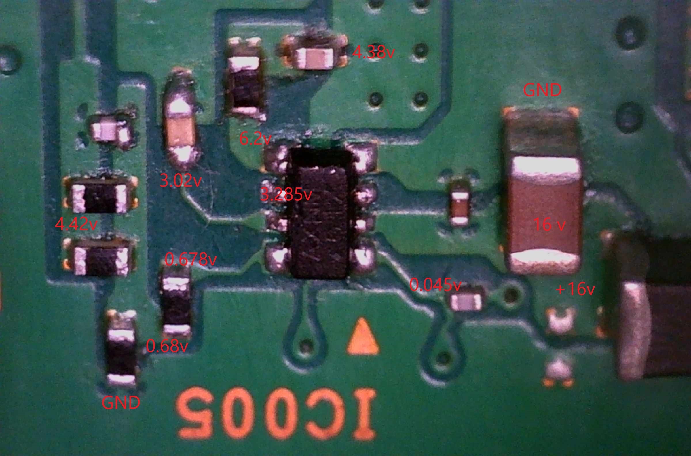
I have attached a photo with voltage measurements.
The input supply voltage is not 16 volts, as shown in the photo, but 16.8 volts.
Unfortunately, my toy oscilloscope cannot measure properly what is happening at the points you indicated. Without a load, there are minor oscillations at the throttle output, strong oscillations at the throttle input, and a sawtooth signal under load.
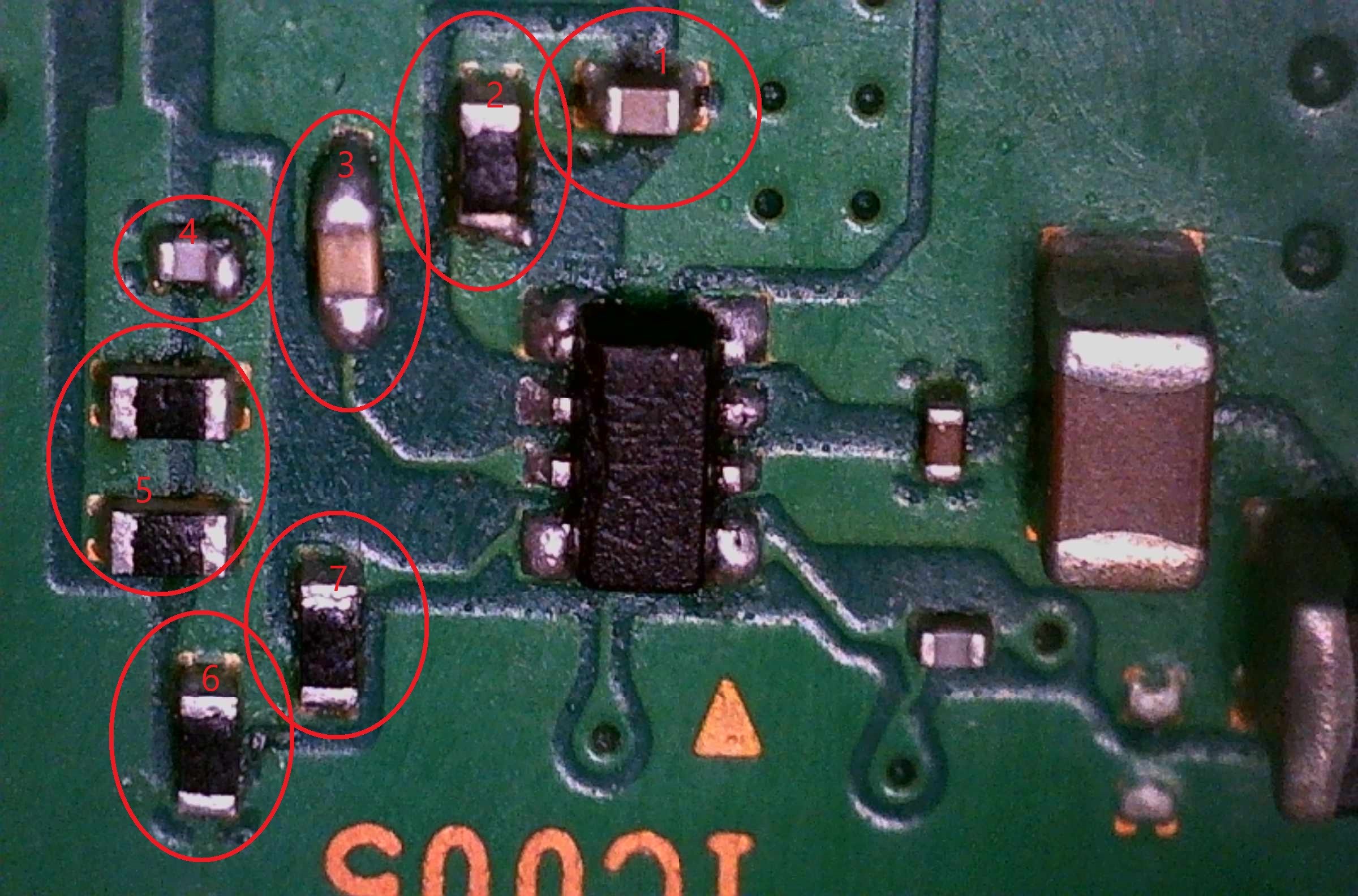
In the photo below, the installed components
- Capacitor - 1 μF (0,888μF)
- Resistor - 22 Ohm
- Capacitor - 6.8 pF (6,78pF)
- Capacitor - I can’t measure it, it’s connected to other components, I need to unsolder it, and most likely my multimeter won’t be able to measure it.
- Resistors - I can’t measure it, they’re connected to other components, I need to unsolder it - The multimeter shows 8.2 kOhm
- Resistor - I can’t measure it, it’s connected to ground, most likely the data is incorrect, I need to unsolder it. The multimeter shows 1.5 kOhm.
- Resistor - 15 kOhm.
Our photo, what my toy oscilloscope shows on the SW pin, at the choke input. No load.

Below is a photo of what my toy oscilloscope shows at the throttle output, where there should be 5.2 volts. No load.

Below is a photo of what my toy oscilloscope shows at the throttle output, where there should be 5.2 volts. With a 7.5 Ohm 10 Watt resistor load.

The service manual I have doesn’t have component values, which makes the task more difficult.
I removed resistors number 5, the top one is 47.2 kOhm, the bottom one is 9.8 kOhm.
In general, I found the reason why the voltage was dropping.
Resistor number 2 in my photo or R4 according to the datasheet should be 20 Ohm, I measured it and it seemed to be 22 Ohm, but when I decided to recheck all the components of the strapping by unsoldering them and measuring the ratings, it turned out that this resistor is not quite stable and one of its terminals has some kind of defect, very poor contact. I replaced it with 24 Ohm and everything worked, it holds a load of 7.5 Ohm easily.
I have one last question, how critical is it to leave 24 Ohm instead of 20 Ohm? The other 3 microcircuits have 22 Ohm resistors.
Thank you again for your support.
Glad to hear your issue was resolved by replacing some of the external components.
The series resistor attached to the bootstrap capacitor essentially is used to slow down the switching speed and reduce the ringing that may be seen by the High Side Switching FET. It is not a critical component, but it plays a significant role in reducing ringing and reducing electromagnetic interference.
This is a small value resistor; I have found even a few ohms can make a significant difference. 24 ohms should be OK and within the resistor tolerance. If the response is too slow or is having issues with stability you can replace the 24 ohms with a 22 ohm resistor.