Hi, I am using MP2338 to generate 5V out of 10V. We are facing a strange Noise and Ripple behaviour on the output. The noise has almost 50-60mVpp or even higher, which is far above the desired ripple budget (ca. 20mVpp). Measurement principle is fine with short ground clip instead of the long probe ground lead. Attached you will find the schematics, which we are using for simulation.
Design is done according datasheet recommendations. Deviations from Datasheet recommendation is the resistor RT, which we have omitted in our design. The resistor is optional according datasheet.

Q1: May this be the root cause for increased ripple and noise, if we omit RT but populate a CFF with 330pF?
Q2: would it be sufficient to remove CFF capacitor in case RT is omitted?
I measured also the FB pin and there was also noise visible. In Simetrix/ Simplis simulation there is no difference visible if the RT is 10k or almost zero. However, this may be related to model limitations (?!)
Hi Andreas. Omission of RT is ok, and a change of Cff value to 330pF from 300pF (assuming you are following the recommended values) should not affect ripple drastically. We would not recommend removing it entirely. Would you mind sharing some output waveform captures so we can help better diagnose the issue? Additionally, please share selected voltage ramp and output capacitance setup.
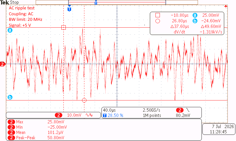
Hello, thanks for your response. Regarding chages to improve the ripple in light load condition I have set CFF to 100pF and reduced the output capacitance from 4x10uF to 2x10uF (X7R ceramic types only). With the original design CFF=330pF and Cout=4x10uF we have noticed ripple of about 51mVpp and random ripple waveforms.
Original design as per datasheet recommendation:
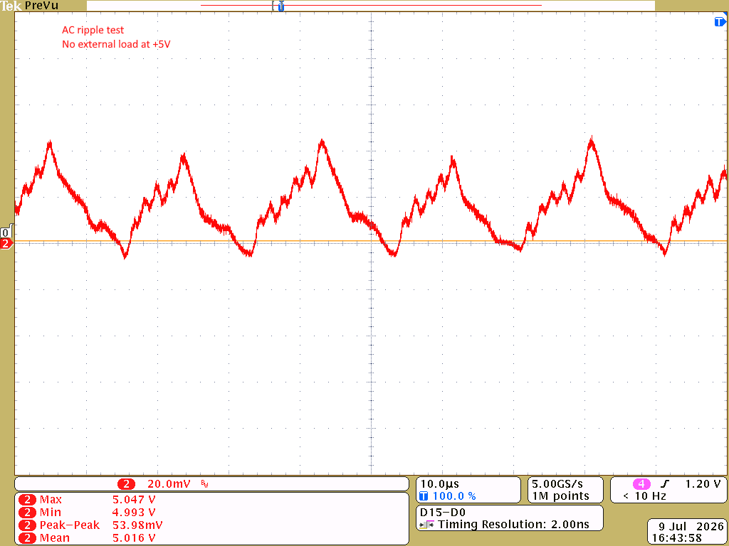
With changed CFF (100pF) and Cout (2x10uF):
This ripple seems to have a more expected ripple waveform with similar ripple amplitude.
If we omit CFF completely the ripple voltage is increased to ca. 185mVpp. So, omitting the capacitor CFF is no option.
Update: I have re-performed the test with CFF=220pF and Cout= 3x10uF X7R. This seems to behave better in terms of ripple than my previous modification. The ripple changes amplitude and signatore (waveform) since we driving isolated CAN transceiver with inbuild isolated switched mode power converters. So the load is quite complex.
Q1: Are there any hints to optimize Cout and Cff without trial and error method?
I think with the current selection I’m quite close to the datasheet recommendation. Unfortunately the MP2338 with COT principle is wrong selected. A standard fixed PWM type would be more suitable.
Q2: Is there a 1:1 replacement option with fixed PWM instead of COT available from MPS?
Thanks in advance!
Best regards, Andreas
Hi Andreas,
Your Cff value is close to the datasheet recommendation; for an output voltage of 5V, we recommend a 300pF capacitor for Cff. Your Cout values will depend on your specific output application, which sounds relatively complex given that it has internal switching converters; on the order of a few tens of microfarads is a good starting point for the tuning process, and then increasing/decreasing depending on the amount of ringing/peak-to-peak overshoot/undershoot.
Can you please describe the deficiency of COT in your current setup? At this point, MPS has no direct replacement for your desired part, but we will let you know if any become available in the near future.
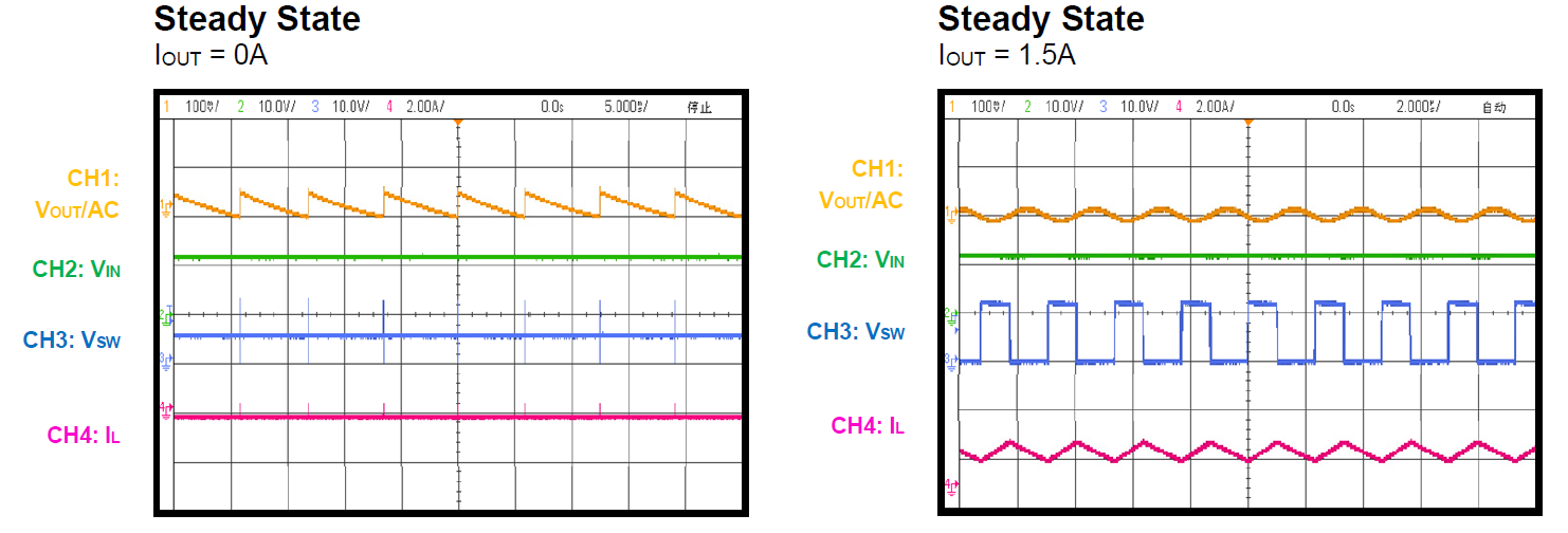
Hello cass, basically no load or very light load condition is the issue with COTs. The ripple is higher due to low switching frequency (PFM mode). This is visible also in datasheet performance diagrams (sawtooth ripple waveform):
So a fixed PWM IC with current mode control would be more suitable for our application with this load variation.
Best Regards, Andreas