Is it possible to use the MP2330H IC for a wide range of inputs between 10 V to 24 V?
Desired input voltage range: 10 V to 24 V in ONE SINGLE DESIGN
My question is:
- Can I design only one single PCB that can accommodate this wide input voltage range?
- My main constraint is that I may have a 12 volt or a 24 volt input. Therefore can I design a single PCB board for this voltage input, without having to change inductors and capacitors for having changed the voltage input?
The desired output voltages needed are (I will probably use one chip each for generating these voltages and currents):
Chip 1. Output voltage 3.3 V, output current 3 A
Chip 2. Output voltage 5 V, output current 1.2 A
Chip 3. Output voltage 12 V, output current 2.5 A
Therefore for 2 possible input voltage levels (10 v to 24 volts), I will have 3 possible scenarios for the output voltage and currents.
Hello coldeepblue,
Please note that this is a buck device. For your 10Vin, 10Vout will not work due to duty cycle constraints. Choosing a buck boost may be a better option for the 10V. A choice could be the MP28167-A.
For the 12V to 24Vin, it should be fine to us the MP2330H. However, you will have varying current ripples. Please design for your worse case to make sure the others will not have current ripple issues.
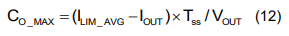
Do not forgot about max capacitance:
Thank you,
Vinh Tran
Hello,
Thanks for you reply, I have further questions after your reply. I would really appreciate it if you can kindly reply faster this time?
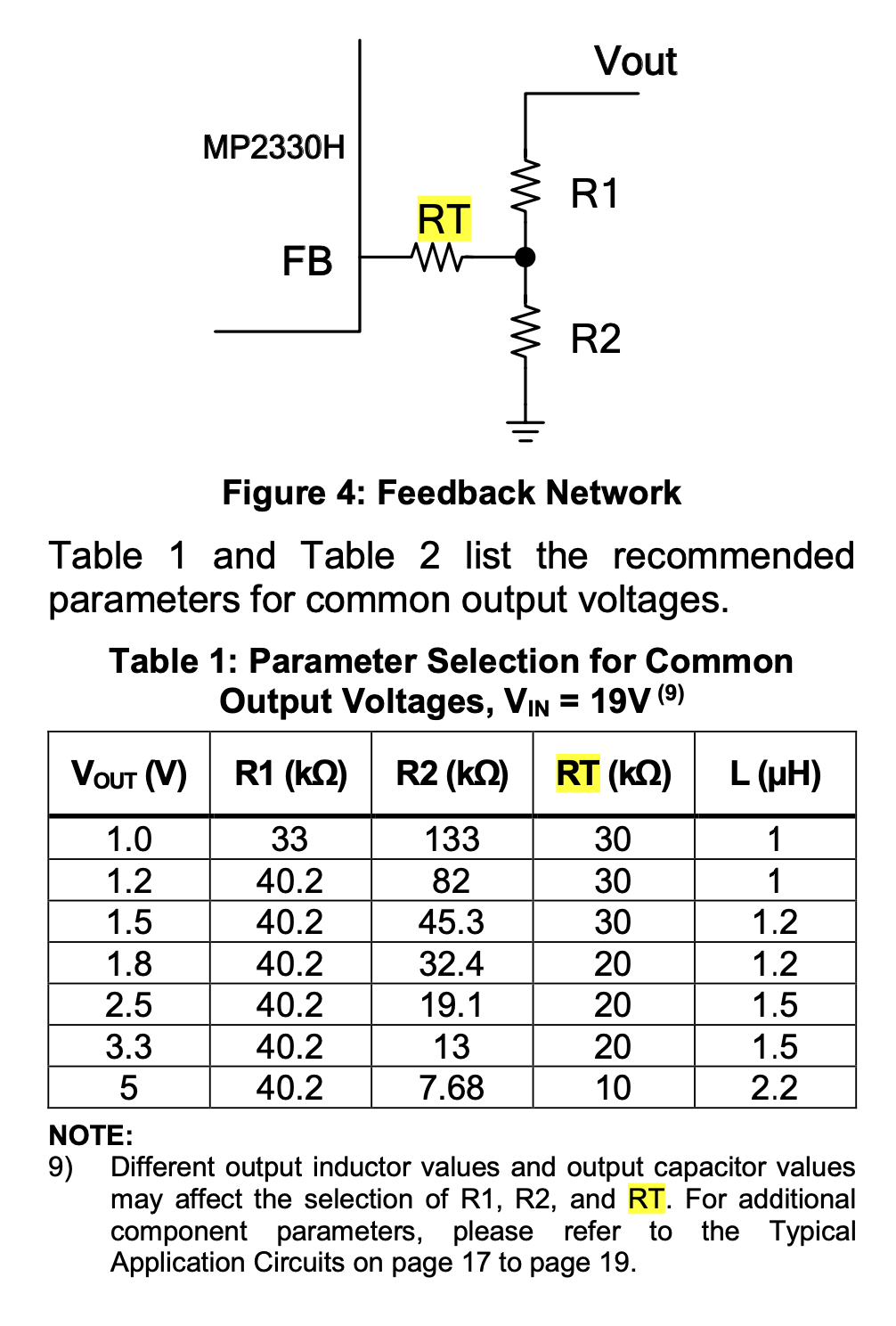
Using the MP2330H chip, for an input of 24 Volt and an output of 12 V, 2.5 A. Using the formula in your data sheet for the voltage divider at the output, having chosen:
R2 = 3 K Ohms,
V_ref = 805 mV,
Vout = 12 V,
I get the value of R1 using the formula in page 14 of the data sheet as:
R1 = 41.72 k Ohms
However, what should be the value of the resistor Rt? There is no formula to calculate the value of Rt, how should we calculate this?
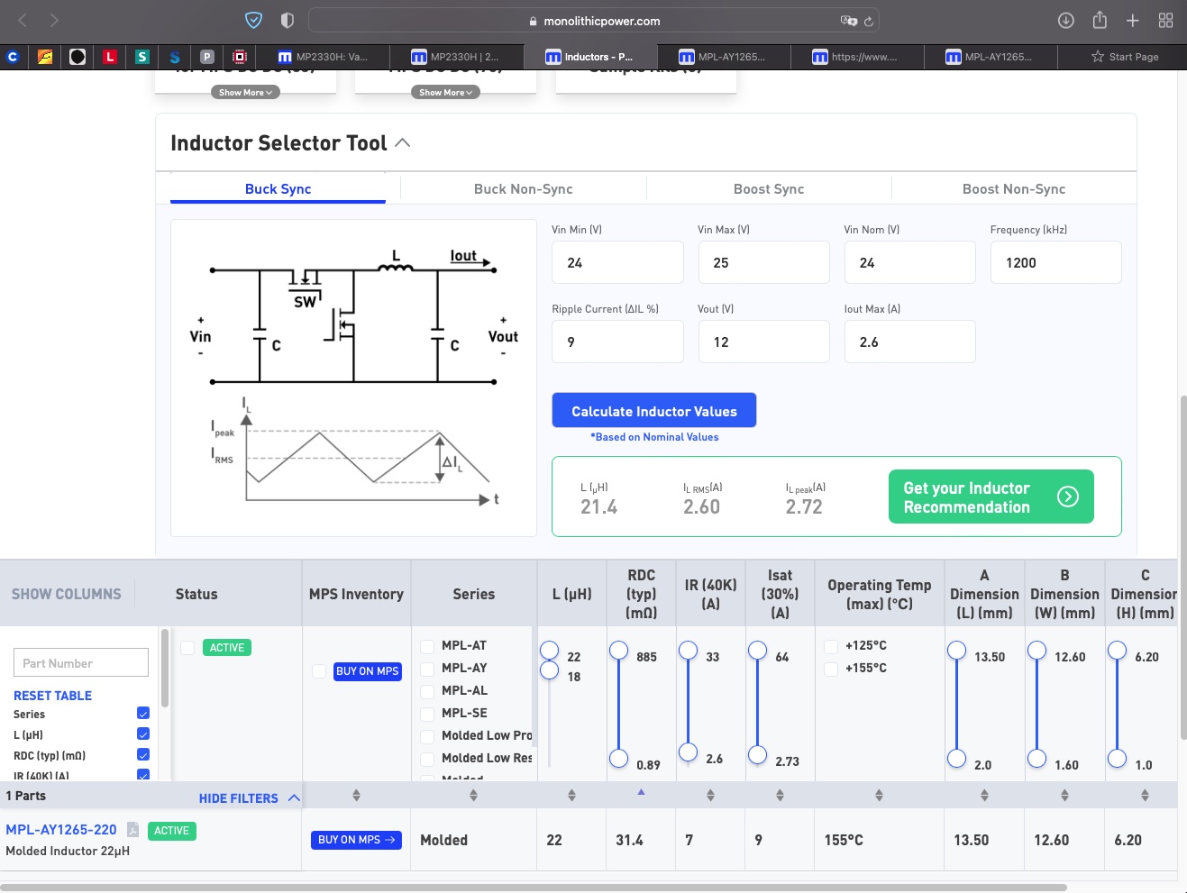
My other design parameters are here.
What should be the value of the Rt, and how do we calculate it?
R1 = 41.72 k Ohms
R2 = 3 k Ohms
Vref = 805 mV
Vout = 12 Volts
L = 21.4 uH
Il_rms = 2.6 A
Hi coldeepblue,
There isn’t a formula to selecting RT, please start with the recommended value in the Typical Application Circuit; then adjust as necessary to achieve your optimal output voltage.
Thanks,
Cindy