Hi,
We are using MP2322 buck regulator. The recommended feedback components in the datasheet for 3.3V is 976kohm (R1), 220kohm (R2), 3.3uH (L), 22pF (C5).
But we are using 1000kohm (R1), 221kohm (R2), 15uH (L), 27pF (C5). Could these values cause stability issues?
During proof of design testing, we added an external load (Resistive and Electronic Load connected via short wires) to check load regulation but when the load is increased to more than 0.1A the output oscillates between 2V-5V. Our input voltage is 15V.
Regards,
Infant Jesuraj
Hi Infant,
Try to follow the design of EV2322-D-00A datasheet. You will find we can not only use one 22pF Cout. You can add a 22uF Cout, then I think the ripple will be much smaller.
Sincerely,
Fox
Hi Fox,
Thanks for the reply. We already have a 22uF Cout. But still the output is heavily unstable for >0.1A.
Is there a way to estimate the gain/phase margin? Since the compensation is internal, we are unable to analyze the stability theoretically.
Thanks, IJ
Hi ifrancis,
I got your point. First I think you should try to follow the values in our reference application. Because the inductance is completely different from our reference. Then if you want to check the PM/GM of your design, you can use MPSmart software to do simulation. If you still have questions, feel free to ask me.
Sincerely,
Fox
Hi Fox,
Sure, I will check the MP Smart software. Thanks.
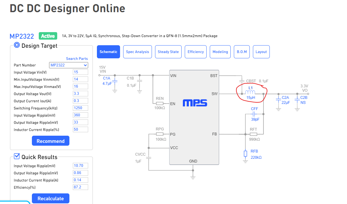
Please note the inductor was selected as per the recommendation in the DC DC Designer Online. The load current in our application is 300mA and the datasheet recommendations were for 1A. Hence, we selected 15uH as per the recommendation in the DC DC Designer online for 300mA output current.
Regards,
IJ
Hi Fox,
The recommended feedback components in the datasheet for 3.3V is 976kohm (R1), 220kohm (R2], 22pF (C5).
Is it ok to use 100kohm (R1), 22kohm (R2], 220pF (C5)? The higher quiescent current due to lower R2 is not an issue in our system. Our aim is to make the feedback as stable as possible. Please let us know what you think.
Thanks,
Infant Jesuraj
You have had 23 days with this, did you try to use the same value of inductor as the demo board, as was suggested? All the other values are within a few percent of the demo board values and one is 5X away from the demo board value. I know which one I would suspect first. Is this your own layout? Cause that could be a problem as well. I would attempt to secure a demo board if I were you.
The inductor is changed to the datasheet’s recommendation of 3.3uH. The query now is regarding only the feedback resistors. Hence the previous query only states"100kohm (R1), 22kohm (R2], 220pF (C5)".
We are ok with higher quiescent current, hence checking if reducing the feedback resistors by 10x is ok or not?