Hi, we are an undergraduate student team in India building autonomous robots, so please excuse our level of understanding.
We aim to build a boost converter module using the MP1542 IC.
Following are the specifications:
- Input - 16.8V (Lithium Polymer 4S Battery)
- Output - 20.4V at 0.5A maximum. (To power an Ubiquiti R5AC-LITE)
In the datasheet for the device it is given that the maximum voltage the EN pin can sustain is 6.5V
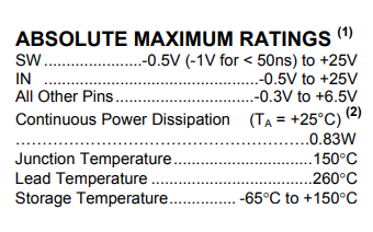
Since our input voltage is 16.8V it was decided to use a voltage divider and bring down the EN voltage to 5V. However in the following text it says that when Vin crosses 6V, the EN pin has to be pulled up to Vin using a 100k resistor
EN - Regulator On/Off Control Input. A high input at EN turns on the converter, and a low input turns it off. When not used, connect EN to the input source (through a 100kΩ pull-up resistor if VIN > 6V) for automatic startup. EN cannot be left floating.
But will the EN pin be able to sustain Vin since it is at 16.8V ?
Thus we are at a crossroads of pulling the EN pin at 5V and at Vin(16.8V). Which one will be feasible?
Regards,
Nilabha
Project MANAS