We are using high power factor driver to run 10W LED load. To switch on/off the light we are using output of 20mW radar sensor through optocoupler. Radar sensor is operated by 3.3 VDC coming from MP100L IC.
Power factor of combined system - LED DRIVER and MP100L supply - is dropped to 0.6. Otherwise Standalone LED driver PF is 0.98.
Input supply is 230VAC, 50Hz. Please suggest a solution to improve the PF.
Under what condition is the PF low? I think what you are saying is when the thing is asleep ( LED off) and the only load is the radar sensor the PF is low.
That is pretty much unavoidable, just the phase shift from the EMI filter is going to drive your PF down. Bad PF at no power isn’t going to be a problem for the grid.
I suspect the problem you have is political, i.e your boss or some regulator thinks PF at no load has to be good. So the task you have is likely one of educating somebody rather than engineering.
PF of combined system (LED DRIVER + MPS SUPPLY) is low when LED load is ON.
Dang! Do you have a sense of how much power the MP100 is putting out? The input side electrolytic cap is what screws up the PF. You might try a parallel charge series discharge arrangement of 2 input capacitors and 3 diodes. ( Peter Wood at IR if I recall) shows this sch in some ap notes. This can get you to about 90% PF.

This is something you might try. Replace the conventional electrolytic with this network. This gives a pf of about .9. You can keep going and add more “series charge” “parallel discharge” stages and increase the pf even more at the penalty of parts count and decreasing valley voltage.
Hi Ops.mowgz:
Can you please share the schematic or block diagram of your system of how the LED driver and the MP100L are connected to the AC Line. Also can you please confirm that the MP100L has only 20mW of load at 3.3V DC Output. So the load current for the 3.3V Output rail of MP100L is only 6-7mA, correct?
If filter is put after rectifier for MP100L then output 3.3 Vdc behaves erratically either zero or starts fluctuating. I replaced the Electrolytic Cap, between VB VD pin and Ground, to above mentioned 2 cap & 3 diode then I achieved the HPF > 0.9.
Even in datasheet there is no filter after recitifer.
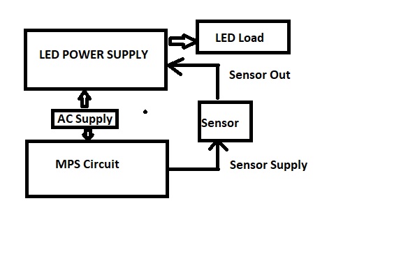
Attached is the block diagram of circuit I am using. I had to use two rectifier, one with filter for LED supply and another without any filter for MP100L IC.
Please suggest if better way.