Hi,
I am considering MP2665AGQB-0000-Z in my new design, can you please confirm the max output peak current supported at the System output,
In my case I will connect the EG916Q-GL module which requires peak current 1.5A to 2Amp
Also What is the voltage level of the I2C and INT pins?
Thank in advanced for your support.
Hi @Sandeep.maurya ,
The MP2665A can provide 3.2A to system load from the battery. This is shown on page 8 of the datasheet:

Battery FET discharge current limit must be configured with I2C in REG03h of the device.
Please Note: Continuous power dissipation is rated to 1.67W at 25C ambient temperature.
SDA, SCL, and INT have an absolute maximum voltage rating of 5.2V.
SDA/SCL are provided by the host. We recommend to use a pull-up resistor to connect INT to VDD.
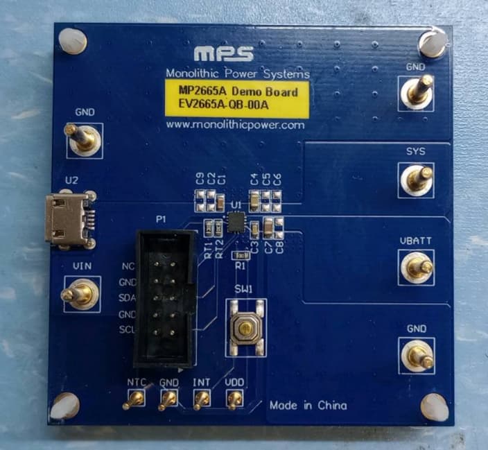
You may find a MPS reference design here: EV2665A-QB-00A.
Thank you, Will
Hi @william.FAE
Thanks for the response,
Please help to clarify below query as well.
Q1-What is the max peak current supported by the IC at SYS when 5V input is supplied at IN pin?
In my case, we will be using GSM LTE Module which required 1.5A to 2A peak,
This will help us to decide whether I can connect my application directly to SYS pin or use the charging feature only.
Q2- Clarity on INT pin interfacing with the host.
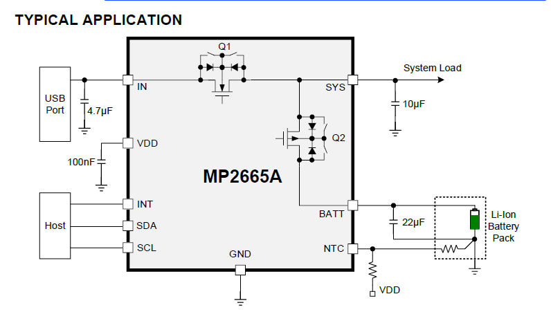
As per the below image from the datasheet (page no.2), INT will be connected to the Host.
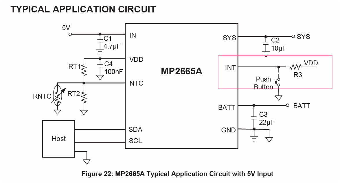
But in Typical application circuit (page no. 39), INT pin is connected to VDD with a pull-up resistor,
but not with the host.
Can we connect the INT Pin with the host?
If yes, what is the voltage level of INT pin, as my host work on 1.8v level.
Thanks!
Sandeep
Hi @Sandeep.maurya ,
I look forward to answering these questions in more detail during our meeting.
Best, Will
Hi @william.FAE ,
Can you please help to clarify about INT pin interfacing with the host?
You may connect INT pin to host.
Note INT pin specifications from datasheet:
- Low logic voltage threshold = 0.4V
- High logic voltage threshold = 1.3V
- Absolute maximum voltage = 5.2V
Thank you, Will
Hi @william.FAE ,
I have the EV2665A-QB-00A evaluation board.
Current test setup:
- 5 V input connected to VIN
- 3.57 V Li-ion battery connected to VBATT
- No load connected to SYS
While testing, I do not observe any charging current into the battery. Could you please confirm whether charging is disabled by default, or if any register configuration is required to enable charging?
I am not getting the Programming tool MP2665A on the MPS website which is recommended in the datasheet to change the settings via I2C.
Could you please provide the download link for the MP2665A GUI/software.
Datasheet link which I refered-https://www.monolithicpower.com/en/documentview/productdocument/index/version/2/document_type/Datasheet/lang/en/sku/EV2665A-QB-00A/document_id/10150/
Hi @Sandeep.maurya ,
I will send you an email shortly regarding the software.
Thank you, Will
Thanks @william.FAE ,
I will be waiting for the software,