Hii,
I have designed an encoder based on MA600 platform. Application requires high accuracy and stability. As per MA600 datasheet, programmed all required parameters (including Calibration). Following are my questions-
- Although calibration is performed with precise reference encoder, still getting error~650-1200 arc sec. (typically 0.2°-0.3°). How can I achieve error < 300 arc sec (< 0.1°) ?
- During validation of my product, I found stability issues in incremental output (Z signal) being triggered randomly at -10°C (Datasheet operating range says -40°C to +125°C). Why this happened?
Hello jedl,
I have several questions:
- Could you share more details about your setup? For example, magnet material and dimensions and sensor position.
- What FW value did you configure? Did you measure the measurement noise?
- Do you obtain the error curve from a single rotation or do multiple rotations and then calculate the average error at for each angle?
- Are you using the TBMA600A? If not, could you share the schematics and layout of your PCB?
- Could you explain in more detail what you mean by “stability issues”? Could you send some oscilloscope screenshots of the Z signal when the issue happens?
Thank you.
BR,
Carmine
Hello Carmine, thank you for considering my query.
Regarding Setup:
Designed PCB is integrated into commercial encoder housing with blind hollow shaft machined out of brass material. An NdFeB N35 grade magnet with 4mm OD and 2mm height is mounted at the end of shaft. Sensor is positioned exactly in the center over the magnet. Air gap between magnet and sensor is 1.7mm.
Regarding Parameters:
FW is set to 12, PPR to 1024. Measurement noise is not recorded but if it is related to harmonics in error curve then it is ~0.03°.
Regarding Calibration:
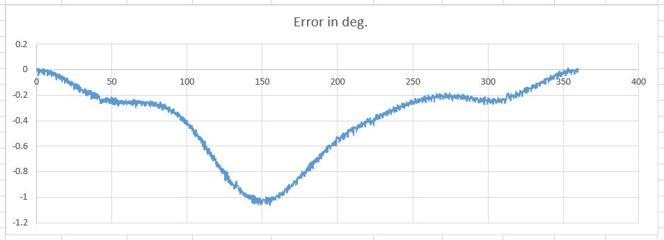
Yes, I have obtained error curve from single rotation but corr (dec) values almost remains same for every rotation. Initial error comes around ~1.1° (4000 arc Sec) but datasheet claims 0.6°.
Regarding Hardware:
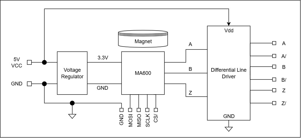
No, I am not using TBMA600A, I had designed circuit around MA600 and interfaced it with 26LS31 kind of line driver IC for differential output. Basic schematic:
Regarding Stability:
During temperature test for (-10°C to 70°C), Z signal was getting triggered randomly only at -10°C temperature. Z-Z edge count sample data recorded at the time was -
975, 4096, 4097, 1587, 4096, 1446, 1873, 549, 4096, 3172. (4096 expected). For remaining temperature range it was constant at 4096.
At low speed (~15rpm) error is 0.15°. At moderate speed (~120rpm) error increases to 0.30°. Accuracy is not stable over speed.
Hello jedl,
Thank you for your detailed response.
I have some additional questions:
- Are the A, B signals still correct at -10°C?
- Currently you are only checking Z from the output of the line driver, correct?
- If yes, is there any way you can look directly at the Z signal generated by the MA600? The purpose of this is understanding if it actually toggles where it shouldn’t or if there is any instability. When doing this test, I would also remove the line driver from the board, if possible.
- Are you sure the line driver can operate at -10°C? I’m asking because some versions of 26LS31, for example, only work between 0 and 70°C.
- How are you measuring the MA600 error? To what sensor are you comparing it to? Is there any time delay between the reference sensor measurement and the MA600 measurement.
BR,
Carmine
A & B signals:
Yes, A & B signals are correct. At 1500 rpm, duty cycle (49.95%) and jitter (1.5usec) for both A & B signals remain the same over the temperature range of -10°C to 70°C.
Signal monitoring:
Yes, I am monitoring all three signals from line driver’s output. The current line driver interfaced with MA600 sensor is proven and validated with other sensors. In fact, we are using them in thousands of quantity.
Line driver:
Driver has operating temperature range of -40°C to 125°C. Actually, it’s not exactly 26LS31 but of a similar kind.
Error measurement:
Reference encoder is a high precision optical encoder with 40960 PPR (163840 counts) and error <0.008°. Both encoders (Ref & EUT) are mounted over single solid shaft on mechanical assembly, designed with precision only for calibration purpose and rotated at ~15 rpm. Reference encoder count is recorded against every single edge event of EUT (from EUT’s Z to Z = 4096 counts). Error is calculated based on deviation in expected and recorded value.
There is an insignificant time delay of only 180 nsec only between edge occurrence and reference position capture, and it’s absolutely fixed for every edge capture event.
Hello jedl,
Could you please run these two experiments:
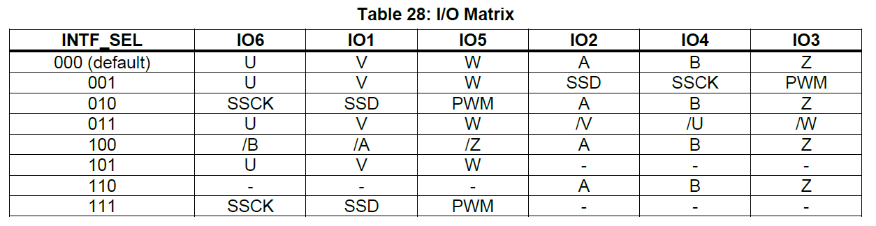
- Configure INTF_SEL = 4, probe signal /Z on IO5 and check if the same issue is present.
- Remove the line driver from the PCB, probe signal Z and check if the issue is still present.
If experiment 2 is hard to run for some reason, it’s ok to start with experiment 1 only.
Did you follow the AVDD and DVDD decoupling recommandations from the datasheet?
Best,
Carmine
Hello Carmine,
I will run experiment and revert back to you with the results. I had followed AVDD and DVDD decoupling guidelines as mentioned in datasheet.
Hello Carmine,
Took multiple trials for temperature testing. Upon changing IO type to ‘4’ as suggested, output is working fine over the temperature range of -10°C to 70°C.
The only issue persist as of now is accuracy. Posting Initial error and after calibration error graph. Can accuracy be improved further?
Before Calibration:
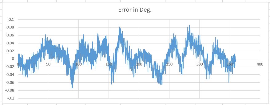
After Calibration:
Regards,
JEDL
Hello jedl,
I’m glad to hear you no longer observe the issue on Z signal.
Regarding the calibration, you have pretty much reached the best possible accuracy.
Best,
Carmine