We are working on tuning an MA102A for Hall sensor emulation.
The Hall output is symmetric when the pole pairs are set at 0 (1 pole pair), but not at any other vale. Increasing the pole pair degrades the symmetry with each increase. At 8 pole pairs, the Hall signal no longer tracks the motor rotation.
Please recommend settings that will improve Hall signal integrity.
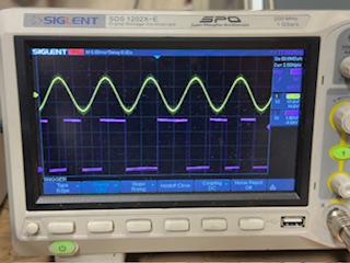
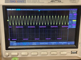
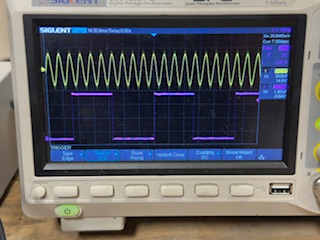
The issue you are experiencing might be caused by a high INL. Could you please send some oscilloscope screenshots of the UVW signals taken at constant speed?
Could you also please share some details about your setup? For example:
A general description
Magnet material, shape, dimensions
Sensor position with respect to the magnet
Is there any ferromagnetic material placed in proximity of the magnet and sensor?
The MA102A is mounted 1.5mm from the N35 diametrically polarized shaft-end magnet.
I checked the magnet to ensure the division of fields was centered. Spinning the motor, the line resolves to a point, not a circle, indicating proper centering. The encoder mounting is 3D printed to center on the shaft. Alignment is within 0.5mm.
Thank you for sharing the information. I would still like to understand if the INL is the root cause of this behaviour (most likely) or there is something wrong with the UVW interface.
We need to measure the INL and to do that we need to either:
Read the MA102 angle output via SPI and compare it to the angle measured with another encoder (e.g. an incremental optical encoder) that is used as a reference.
Spin the motor at a constant speed and read the MA102 angle output via SPI at a fixed sampling rate. Having a constant speed allows us to estimate the shaft angle at each instant when the MA102 output is read. We obtain the INL by comparing the MA102 output to the shaft angle estimate.
Is it possible for you to perform any of these two measurements?
I’ll try and coordinate dual encoders and their prospective SPI outputs to generate a table of values.
I will also try just moving the encoder to see how different positions affect the UVW output, no problem.
What is puzzling is how the symmetry shifts from 50% duty cycle at 1 pair, to chaos at 2 and above. This implies the INL signal would be dependent on the pole count…?
I was contacted by my local salesman to engage in a Teams meeting to solve the problem. In preparation, I did some experimentation using a drill and tube to spin a magnet off axis to check your diagnosis. When the sensor was in my hand, I saw that the carrier board is indeed mounted off center within the mount. With the magnet spinning on axis, the Hall signal was spot on for a 50% duty cycle. In addition, the engineers in the meeting explained how to adjust the offset to compensate for the axial misalignment.
This allows me to move forward with development of an encoder cassette on a new project, very satisfying.
Thank you for your support. You called it right off, I’ll double check my installation at your first suggestion next time…
Please consider this case closed.