im having an issue with the MP28167GQ-A-Z chip where a valid 5v is applied to vin and when i turn on the ic trough a switch connected to the EN pin, it outputs 3.3v for a fraction of a second, fully draining th 100uf capacitor and the voltage drops to 2.06v on Vin and 200mv on Vout until i turn it off trough EN and it goes back to 5v. my setup for resistors is r1=246k, r2=107k, rT=887k and L=4.7uh. the rest is all pretty much identical to the reference design. note that it is staright out of the package, no i2c programming has been done and i cant do any unless it outputs 3.3v since its powering the mcu
Hello,
Thanks for reaching out.
Sounds like there is a protection that the IC/input supply is hitting as the IC is enabled. Can you please provide a schematic? Is the 5V coming from another IC or is it an external supply? Can you supply any waveforms during the EN sequence you described (Input, Output, Load, and SW Node)? Also probing VCC and BST can be helpful.
First, I would make sure the over currents are set properly on the IC according to your system, then I would check the current and voltage limits of your supply.
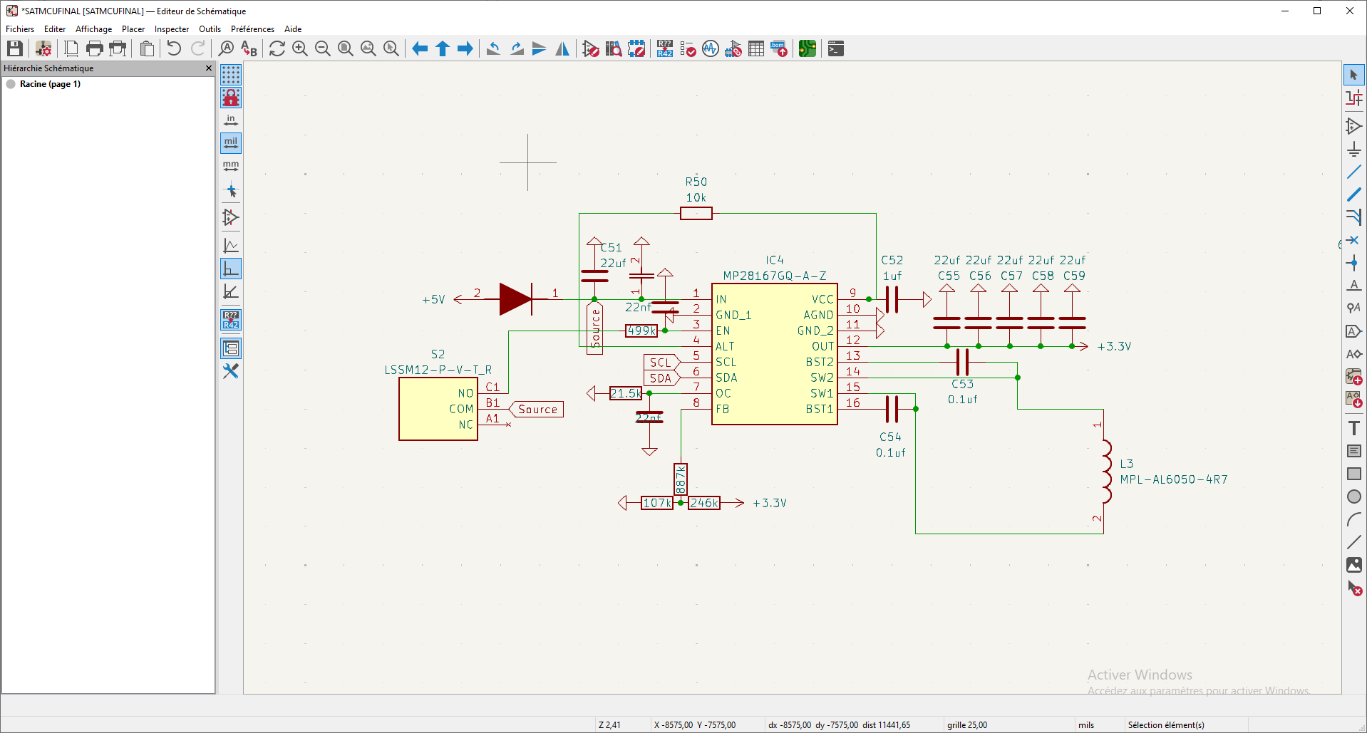
hi, thanks for your reply. here is a schematic. 5v is coming from usb port. i dont have a oscilloscope so i cant help on that. VCC is at around 2v and bst is at 1.63v when EN is pulled high. i doubt there it is an overcurrent problem unless there is a short (doubt it, no heat emission) because there is literally no other components other than the mp28167 and the resistors on the board, so nothing is drawing any significant amount of current. Also it seems the voltage i get on vin when enabled is the same as vcc as if they were internally connected.
Hello,
Thanks for providing the schematic. I reviewed your schematic and the connections look OK. The only differences I see are the feedback resistors. The waveforms would indicate what kind of behavior the part is in, as DC measurements don’t provide information regarding the switching behavior of the part. Without a scope we are limited to the DC measurements and register settings.
The behavior you described indicates to me an OCP. When the output current exceeds the current limit threshold, the output voltage will drop. To fix this, a power cycle via enable pin/bit or Vin will bring the IC back, see pg 20. Please check the protection registers, CTL1 and CTL2.
To debug on hardware, I can recommend first trying to get the 5V application first, pg 30, and verify it operates correctly. If it does, there may be mismatch between the I2C registers and your hardware. I would also check the register settings to ensure the VREF_L and VREF_H, VREF_GO, and the LINE_DROP_COMP are set appropriately.
the output voltage doesnt drop, no voltage is outputed really, its the input voltage that gets dropped
just tried running it with the 5v setup and same thing happens, onyl thing is the voltages are slightly higher but still no ouput
i tried different ics too
alright little update, i tried finecking with it and it worked out of nowhere just by turning it on and off and now it works reliably kind of… i dont know what caused it tho. only thing i changed is i bypassed the diode. could it be the problem?
Thanks for clarifying, my mistake in understanding of the problem you are seeing. Sounds like a UVLO latch off. The part will turn off if the input voltage falls below 2.65V. VCC being 2V would indicate some supply issue. If the diode were there, it is possible some characteristic of your specific diode could have limited the input.
ill try that in the main board and come back to you
alright yep that was the problem, thanks for your help buddy, it might not seem like it, but just talking about a technical problem helps resolving it. Cheers!
1 Like
Just quickly, the diode im using is the B130LAW-7-F whats causing the problem with the converter? ive used it with other ics before and it worked just fine.