We’ve had a number of failures of MPL-AL5050-8R2 inductors when used in a 2A, buck regulator design with a 12-60V input and 5V output. It’s been suggested that the inductor is failing due to the high input voltage, although this parameter isn’t specified on the datasheet. The original regulator reference design uses a Coilcraft XAL5050-822 which does specify a maximum voltage of 60V.
Is this a likely failure mode?
Hi Mike,
Welcome to MPS forums, sorry to see that you are having issues with MPL-AL5050-8R2.
- What kind of failures are you observing with the inductor, is it saturating?
- Can you send the waveforms such as inductor current and switch node for better understanding?
- What is the regulator part number you are referring here to and the switching frequency?
Regards,
Adhish
After replacing the inductor the regulator appears to work ok. Measuring the inductance of the removed device is showing a significant reduction - down to 2uH or less in some cases.
The regulator we are using is a Maxim/Analog Max17783C, running at 500kHz.
These products have all passed our basic production test where they have a brief test at 12V and also at 55V input. It’s only during operation that we have seen the failures.
I have a number of waveforms that I can share, although not sure how I can include them in this post?
Hi Mike,
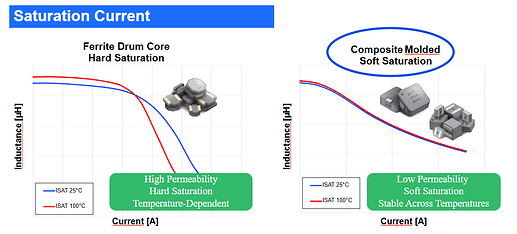
It may be a lot/batch issue then. That sounds very strange when you say it drops to 2uH. The MPL-AL series are molded inductors which follows the soft saturation and not hard saturation.
Is your ambient temperature too high?
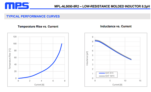
Based on our collected data, the part shouldn’t be going so low with your maximum load current of 2A.
We have an article based on how to avoid saturation in inductors that you can take a look as well. Here is the link: How to Avoid Inductor Saturation in your Power Supply Design | Article | MPS. Check out Method 2 to Method 4.
For sending the waveforms, there should be an icon for attachment in your comment section that you can add your files.
Regards,
Adhish
Hi,
The faults have occurred with 3 different manufacturing partners/batches (2 prototype stages and a production stage) and with components probably bought from 3 different sources so unlikely to be a batch related issue.
The current in our system is also below the maximum for this regulator so we should be well under the design current limits.
Also, regarding ambient, most of these have failed during initial configuration/setup in an office environment, before being installed on site, so again unlikely to be temperature related.
Some traces attached here.
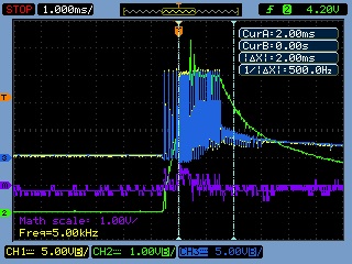
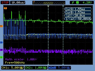
File 20 – Green shows Vo. Yellow/Blue are across a sense resistor (500mR) at inductor to measure current. Purple is maths function showing voltage difference, and hence current.
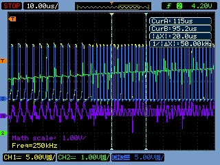
21 – Zoom in to the ramp up point where switching frequency changes from 250 → 500kHz.
22 – Zoom in at steady voltage where switching decrease and Vo starts to decrease presumably as a result of probable fault situation.
Not sure any of these show a significant current through the inductor to indicate saturation.
The Maxim regulator has overcurrent limiting on a cycle by cycle basis of about 4A which should be well under saturation levels.
