- 3.3V Output Consistency: I’m using the MP2393 IC with the components specified in the datasheet, but I want to confirm if this setup should consistently provide a stable 3.3V output. Are there any adjustments or considerations I should keep in mind to ensure accuracy?
- VIN and EN Pin Resistor: I noticed that a 604kΩ resistor is placed between the VIN and EN pins. Could you explain the purpose of this resistor? Why is it necessary to use this specific value, and how does it impact the performance of the power supply?
Hello harshadchavan990,
Responding to bullet point 1:
This should consistently output 3.3V. However, there are some considerations for designing a switching regulator such as this one. The voltage ripple will be the variation in the voltage you see at the output. The current ripple is the fluctuation of current as seen by the charging and discharging of the inductor. I am providing the following links which explain the sizing of the inductor and output capacitor for this type of converter and how they affect the behavior.
Buck Converters (Step-Down Converter)
How to Calculate a Buck Converter’s Inductance | Article | MPS
Answering the bullet point 2:
The resistor placed between Vin and EN pin is used to pull the voltage of the enable up to the input voltage. This allows for the MP2393 to begin operation when there is an input voltage since EN is a digital control pin that turns the regulator on and off. The enable pin does not always need to be connected in this way for operation. The specific resistor value is referenced in the datasheet on page 12 under Enable Control (EN). It also takes you through a calculation of the current seen by an internal zener diode that specifies a max current of 30uA. The value was simply chosen to prevent damaging this pin.
Additional Information:
We have layout guidelines available in the datasheet for design.
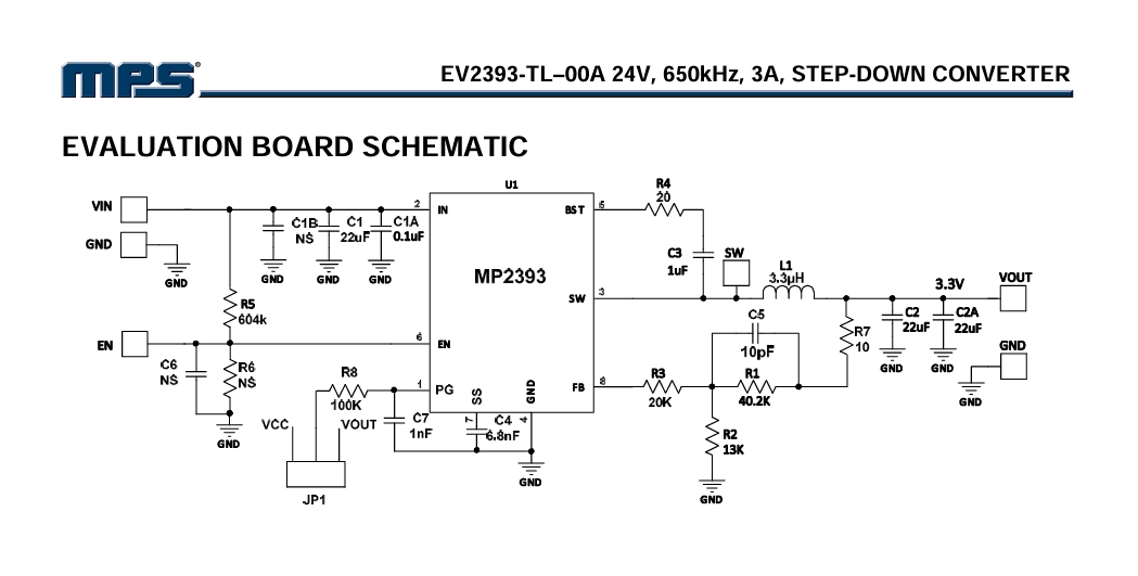
I also recommend looking at the evaluation board for the MP2393: EV2393-TL-00A | High-Efficiency, 650kHz,3A, 24V. Step-Down ConverterEvaluation Board | MPS
Let me know if you have any other questions or if you are interested in other resources.
1 Like
Question:
The evaluation board for the MP2393 uses specific components to produce a stable 3.3V output with a 3A current capacity. Can you explain the role of each key component (e.g., inductors, capacitors, resistors) in maintaining the 3.3V output stability and ensuring sufficient current handling? Specifically, how do the values of (3.3 µH) and the capacitors , (22 µF each) influence the output voltage ripple and overall performance?
Hello harshadchavan990,
Please carefully read through pages 15-16 in the datasheet for MP2393. This provides information regarding the role of each key component and how they influence behavior. These pages cover how to setup desired output voltage by resistors connected to FB, the sizing of the inductor and rules of thumb used, the sizing of input and output capacitors.
Please let me know if you need anything clarified from the content in the datasheet.
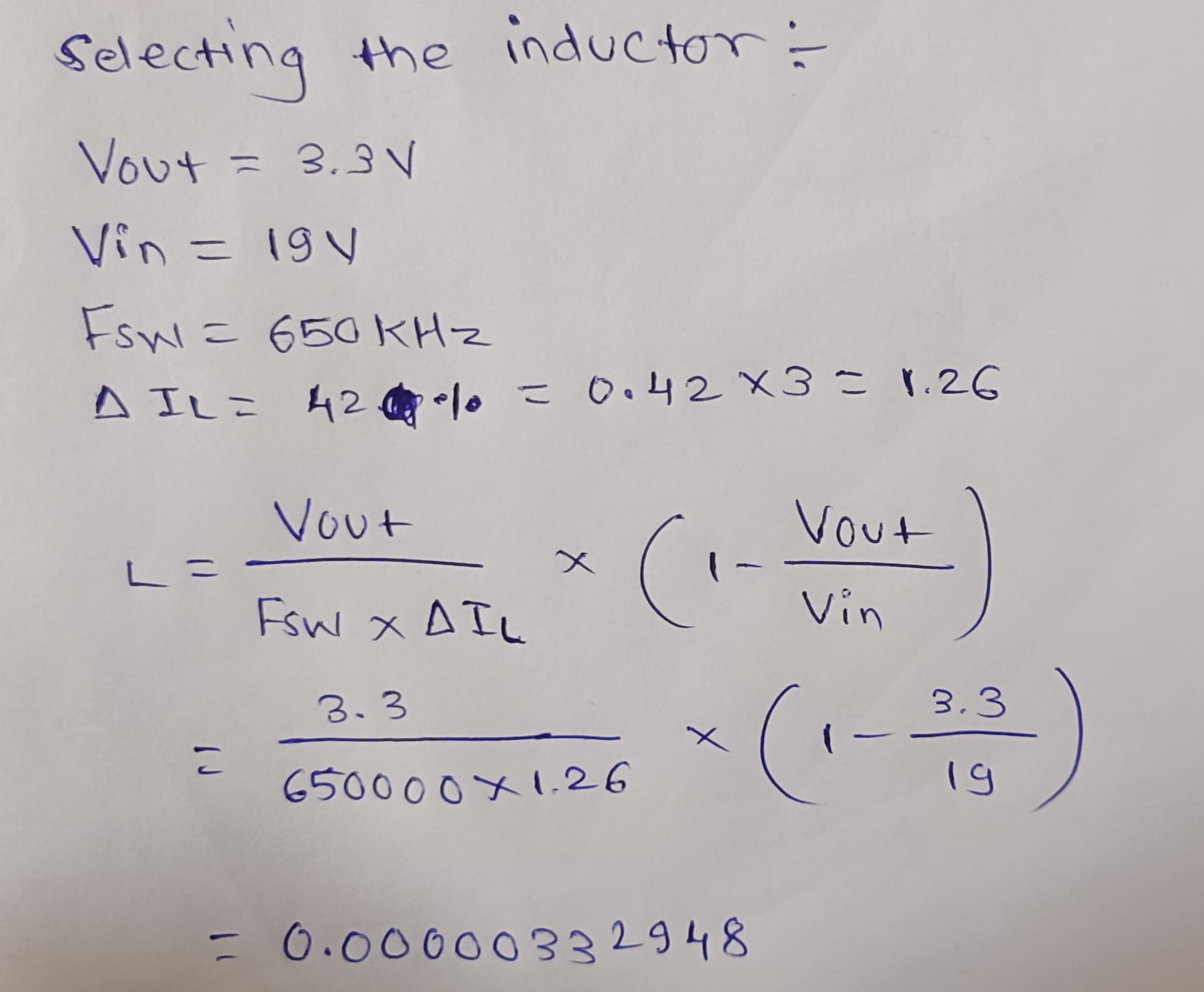
I am working on selecting an inductor for a power supply circuit based on the datasheet’s guidelines. Can you help me understand the correct formula to use for calculating the inductance value, and how to determine if my approach to solving it is correct?
Coilcraft has a simply fantastic DCDC optimizer tool that will do all these calcs for you and suggest dozens of parts and calculate their losses and temperature rises.
I couldn’t be bothered to review you calcs but you want a dI of 1.26 A in a dt of (3.3/19) *1/fsw
And L = V di/dt where V is 19-3.3
This topic was automatically closed after 2 days. New replies are no longer allowed.