Hello, I am studying HR1211GY IC to use on my battery charger 600W (14.8/40A).
Currently I’m stuck with the proper peripheral component values of my CSHB and CR.
I understand that CSHB is for current sense through Rs (resistor across the pin), but I don’t know how to properly set the RC on the pin, as I noticed that when I remove a load on my power supply there’s a hiccup sound-like on it (and my Vout is a little unstable), and when I changed RC there’s a slight difference on it but I don’t really understand this behaviour.
While for the CR pin, when I set Cr1=220pF, Cr2=20nF, I can’t turn-on my smps if there’s a load on it, can only turn-on if I initially turns-on with no load first and then add a load, may I know why is this? If I lower the Cr2, it solves that problem but notice that I can’t reach the designed full Pout.
I hope someone can help me on this.
Thank you so much in advance.
Hello,
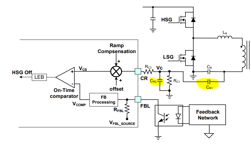
The issues that you are dealing with for the HR1211 (embedded link to Datasheet) may come from the roles the CR (Compensation) & CSHB (Current Sense) pins.
CR Pin: Responsible for sensing the divided resonant capacitor voltage to determine the LLC switching frequency. Components connected here have an influence on the loop stability and transient response of your IC.
- When Cr1 = 220pF & Cr2 = 20nF yielded the SMPS to not turn on, this may be indicative of this compensation network not being correctly configured.
- If lowering Cr2 helps with startup under a load, this may have been indicative of your original values yielding a slow transient response. At the same time, reducing Cr2 limits your output power and decreases stability in maintaining full power output.
CSHB Pin: This pin uses a current sense resistor or a capacitive divider to sense the primary side current. The RC network connected to this pin acts as a filter to ensure high-frequency noise does not affect the stability of the current going back to the feedback of the IC isn’t affected.
- The hiccup sound that you can hear alongside the Vout instability are indicative of improper filtering of the CSHB pin.
- Too much filtering may cause slowed down response time which would delay the reaction of the IC to load changes. (This could be what you are seeing when lowering Cr2?)
- Too little filtering would let high frequency noise through, yielding instability.
Tweaking the components alongside observing system behavior is a good start, but the following should be done:
- Calculating your RC values based on your switching frequency while monitoring stability and response of your IC. You are gonna want to find a balance between stability and not adding too much delay.
- Using standard compensation values, observe the startup and stability at full-load conditions by experimenting and optimizing your Cr1 & Cr2 capacitors. See page 27 of the datasheet for more details on the stipulations for the ratio these components should be at.
Now I know I threw a lot of information at you. And debugging this will most certainly be tedious. But start with your calculations for the RC filter as it is a function of your switching frequency. Then adjust Cr1 & Cr2 from there.
Hope this helped,
Krishan
1 Like
Thank you Mr. Krishan for very informative and clear response, I will try your advice, at least now I have a path to take.
Hi Mr. Krishan, while I’m at it, may I ask also if there’s really a recommended value for Cr1? Because my supplier said I need to set Cr1 as 220 pF when it is over 400W application, while for less than 400W use 100 pF for Cr1, but he didn’t mention why. May I confirm if this is really the recommended value for this application, so I can only change the Cr2?
For the RC filter of CSHB, so my priority here is to have just enough filter that will solve my hiccup sound (whenever I remove the load from loaded condition), and then from that adjust the Cr2 and feedback compensation value to make it fast enough in terms of transient response, right?
Thank you again.
Since you are using this IC at 600W, then you should stick to Cr1 = 220pF if your supplier tells you and decrease Cr2 as you said.
But yes, as for the RC Filter, start with calculating these values such that you are filtering properly such that you won’t audibly hear anything and such that it would be a function of your switching frequency.
And no problem, happy to be of some assistance.
1 Like
Ok I understand, I’ll try to work it out from all of these information. Thank you again Mr. Krishan.
1 Like